ECD SYSTEM (w/ DPF) Pre-heating Control Circuit
DESCRIPTION
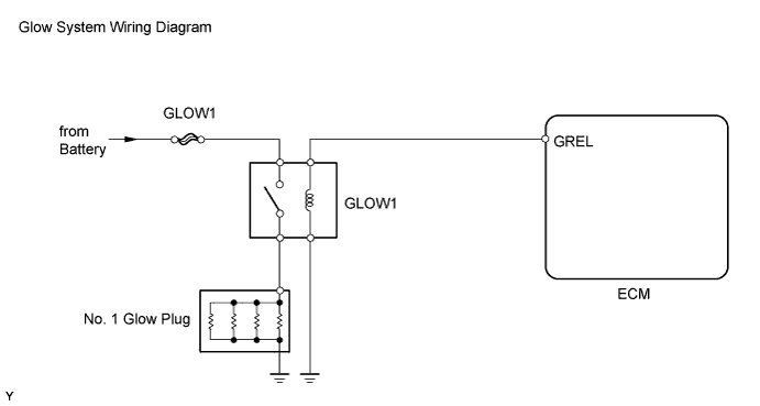
The glow plug is mounted inside the engine combustion chamber. To ensure efficient engine starting with a cold engine, the ECM calculates a time interval of the current that needs to flow through the glow plug depending on the starting engine coolant temperature when the engine switch is turned on (IG). The ECM then turns on the glow relay and permits current to flow through the glow plug based on the ECM calculated time. The glow plug is then heated, and enhances fuel combustion with a cold engine.
A DTC will be stored if the glow plug or the circuit is open.
Tech Tips
-
These troubleshooting procedures are for: 1) difficult engine starting in cold weather, and 2) difficulty driving/vehicle malfunctions in cold weather immediately after engine is started.
-
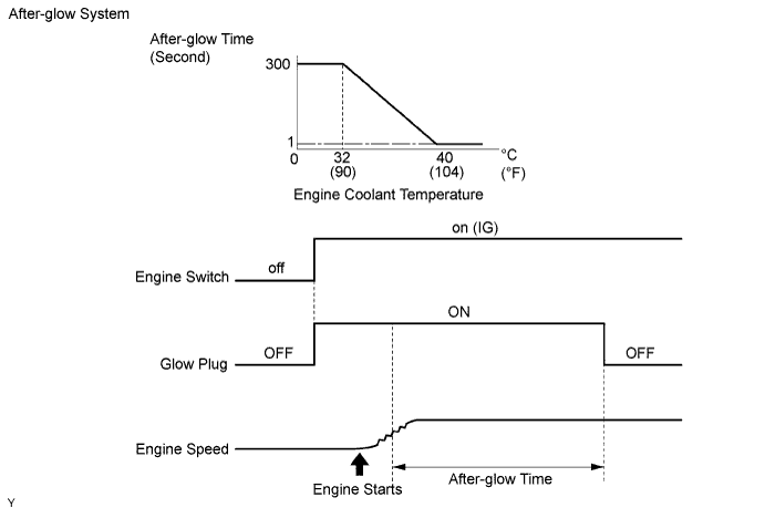
After the engine is started, the ECM performs "after-glow" for a certain period of time. In proportion to the actual engine coolant temperature, the time period varies. The after-glow reduces diesel engine knocking, white smoke emissions and engine noises when the engine is cold.
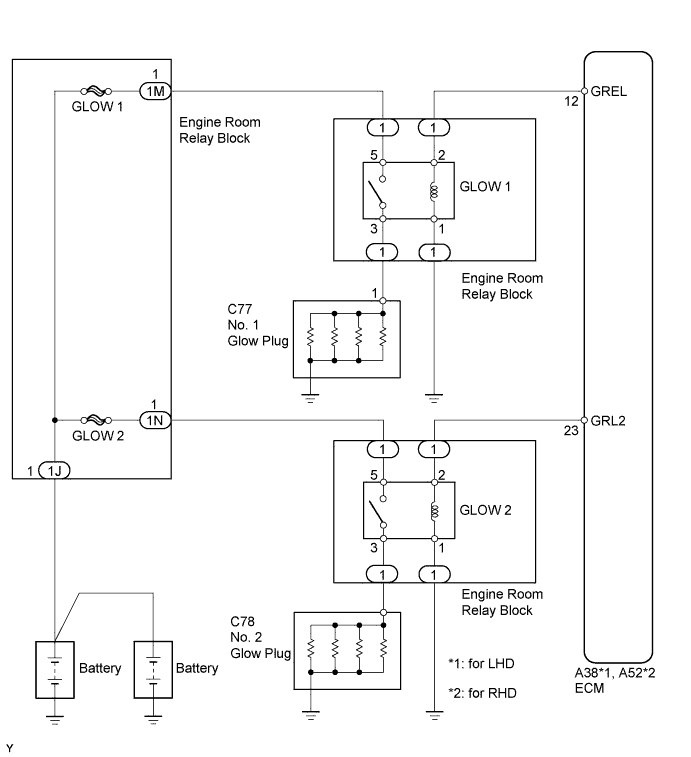
WIRING DIAGRAM
INSPECTION PROCEDURE
Note
-
Inspect the fuses of circuits related to this system before performing the following inspection procedure.
-
After replacing the ECM, the new ECM needs registration Click here and initialization Click here.
PROCEDURE
-
CHECK ECM TERMINAL VOLTAGE (GREL TERMINAL)
-
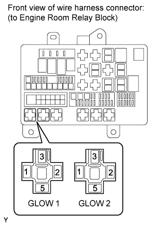
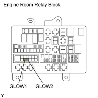
Remove the GLOW 1 relay from the engine room relay block.
-
Remove the GLOW 2 relay from the engine room relay block.
-
Measure the voltage according to the value(s) in the table below.
Standard Voltage Tester Connection Switch Condition Specified Condition GLOW 1 relay (2) - Body ground Engine switch on (IG) 11 to 14 V GLOW 2 relay (2) - Body ground Engine switch on (IG) 11 to 14 V
NG 
CHECK HARNESS AND CONNECTOR (GLOW PLUG RELAY - ECM AND BODY GROUND) Click here
OK 
-
-
INSPECT GLOW RELAY (GLOW 1 or 2)
-
Inspect the GLOW 1 relay Click here.
-
Inspect the GLOW 2 relay Click here.
NG 
REPLACE GLOW RELAY (GLOW 1 or 2)
OK
-
-
INSPECT FUSE (GLOW 1 and GLOW 2)
-
Remove the GLOW 1 and GLOW 2 fuses from the engine room relay block.
-
Measure the resistance according to the value(s) in the table below.
Standard Resistance Component Condition Specified Condition GLOW 1 H-fuse Always Below 1 Ω GLOW 2 H-fuse Always Below 1 Ω
NG
CHECK FOR SHORT IN ALL HARNESSES AND COMPONENTS CONNECTED TO FUSE, AND REPLACE FUSE
OK
-
-
INSPECT GLOW PLUG ASSEMBLY (RESISTANCE)
-
Inspect the glow plug assembly Click here.
NG
REPLACE GLOW PLUG ASSEMBLY Click here
OK
-
-
CHECK GLOW PLUG ASSEMBLY (INSTALLATION)
-
Check the glow plug installation Click here.
OK Glow plugs are installed securely.
NG
TIGHTEN GLOW PLUG Click here
OK
-
-
CHECK HARNESS AND CONNECTOR (GLOW PLUG RELAY - GLOW PLUG - BATTERY AND BODY GROUND)
-
Remove the GLOW 1 relay from the engine room relay block.
-
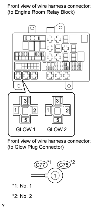
Disconnect the C77 glow plug connector.
-
Measure the resistance according to the value(s) in the table below.
Standard Resistance (Check for Open) No. 1 Tester Connection Condition Specified Condition GLOW 1 relay (3) - C77-1 Always Below 1 Ω GLOW 1 relay (5) - Positive (+) battery terminal cable Always Below 1 Ω GLOW 1 relay (1) - Body ground Always Below 1 Ω -
Remove the GLOW 2 relay from the engine room relay block.
-
Disconnect the C78 glow plug connector.
-
Measure the resistance according to the value(s) in the table below.
Standard Resistance (Check for Open) No. 2 Tester Connection Condition Specified Condition GLOW 2 relay (3) - C78-1 Always Below 1 Ω GLOW 2 relay (5) - Positive (+) battery terminal cable Always Below 1 Ω GLOW 2 relay (1) - Body ground Always Below 1 Ω
NG
REPAIR OR REPLACE HARNESS OR CONNECTOR
OK 
CHECK FOR INTERMITTENT PROBLEMS Click here
-
-
CHECK HARNESS AND CONNECTOR (GLOW PLUG RELAY - ECM AND BODY GROUND)
-
Remove the GLOW 1 relay from the engine room relay block.
-
Remove the GLOW 2 relay from the engine room relay block.
-
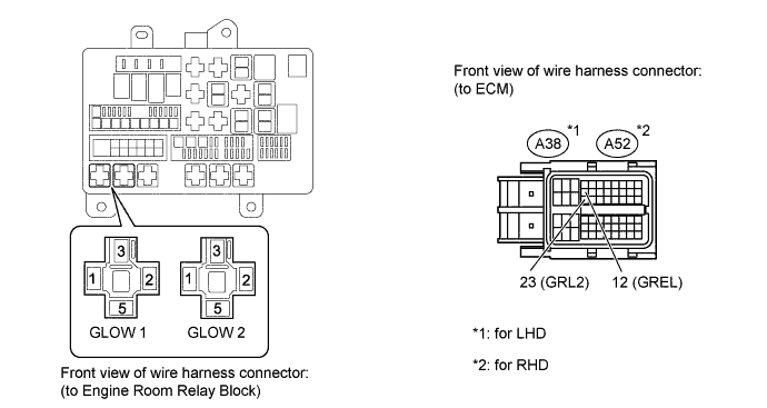
Disconnect the ECM connector.
-
Measure the resistance according to the value(s) in the table below.
Standard Resistance for LHD Tester Connection Condition Specified Condition GLOW 1 relay (2) - A38-12 (GREL) Always Below 1 Ω GLOW 2 relay (2) - A38-23 (GRL2) Always Below 1 Ω GLOW 1 relay (2) or A38-12 (GREL) - Body ground Always 10 kΩ or higher GLOW 2 relay (2) or A38-23 (GRL2) - Body ground Always 10 kΩ or higher for RHD Tester Connection Condition Specified Condition GLOW 1 relay (2) - A52-12 (GREL) Always Below 1 Ω GLOW 2 relay (2) - A52-23 (GRL2) Always Below 1 Ω GLOW 1 relay (2) or A52-12 (GREL) - Body ground Always 10 kΩ or higher GLOW 2 relay (2) or A52-23 (GRL2) - Body ground Always 10 kΩ or higher
NG
REPAIR OR REPLACE HARNESS OR CONNECTOR
OK
REPLACE ECM Click here
-