CLEARANCE WARNING BUZZER REMOVAL
PROCEDURE
-
PRECAUTION (for Multi-Media Module Receiver Type)
Note
After turning the power switch off, waiting time may be required before disconnecting the cable from the negative (-) auxiliary battery terminal. Therefore, make sure to read the disconnecting the cable from the negative (-) auxiliary battery terminal notices before proceeding with work Click here.
-
CUSTOMIZE POWER TILT AND POWER TELESCOPIC STEERING COLUMN SYSTEM (for Power Tilt and Power Telescopic Steering Column)
-
REMOVE LUGGAGE TRIM SERVICE HOLE COVER (for Multi-Media Module Receiver Type)
-
DISCONNECT CABLE FROM NEGATIVE AUXILIARY BATTERY TERMINAL (for Multi-Media Module Receiver Type)
Note
When disconnecting the cable, some systems need to be initialized after the cable is reconnected Click here.
-
REMOVE INSTRUMENT CLUSTER FINISH PANEL SUB-ASSEMBLY
-
REMOVE CENTER INSTRUMENT CLUSTER FINISH PANEL GARNISH
-
REMOVE NO. 2 INSTRUMENT PANEL REGISTER ASSEMBLY
-
REMOVE LOWER CENTER INSTRUMENT PANEL FINISH PANEL
-
REMOVE RADIO RECEIVER ASSEMBLY WITH BRACKET (for Radio Receiver Type)
-
REMOVE MULTI-MEDIA MODULE RECEIVER ASSEMBLY WITH BRACKET (for Multi-Media Module Receiver Type)
-
REMOVE NO. 1 CLEARANCE WARNING BUZZER
-
for LHD:
-
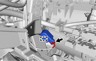
Disconnect the connector.
-
Disengage the clamp and remove the No. 1 clearance warning buzzer.
-
-
for RHD:
-
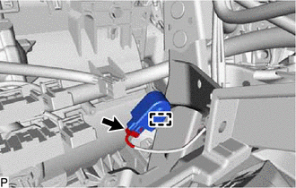
Disconnect the connector.
-
Disengage the clamp and remove the No. 1 clearance warning buzzer.
-
-