PROCEDURE
- Click here
INSTALL TIE ROD ASSEMBLY LH
-
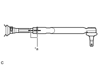
Install the lock nut and tie rod assembly LH to the steering rack end sub-assembly until the matchmarks are aligned.
Table 1. Text in Illustration *a Matchmark Tip:After adjusting the front wheel alignment, tighten the lock nut.
-
- Click here
INSTALL TIE ROD ASSEMBLY RH
Tip:Perform the same procedure as for the LH side.
- Click here
INSTALL STEERING LINK ASSEMBLY
-
Install the steering link assembly with the 2 bolts and 2 nuts.
70 N*m 714 kgf*cm 52 ft.*lbf Note:
-
Keep the nut from rotating while turning the bolt because the nut has its own stopper.
-
Make sure to tighten the bolts starting from the pinion shaft side.
-
-
- Click here
INSTALL FRONT STABILIZER BAR
- Click here
INSTALL FRONT NO. 1 STABILIZER BRACKET LH
- Click here
INSTALL FRONT NO. 1 STABILIZER BRACKET RH
Tip:Perform the same procedure as for the LH side.
- Click here
INSTALL ENGINE ASSEMBLY WITH TRANSAXLE
- Click here
CONNECT TIE ROD ASSEMBLY LH
-
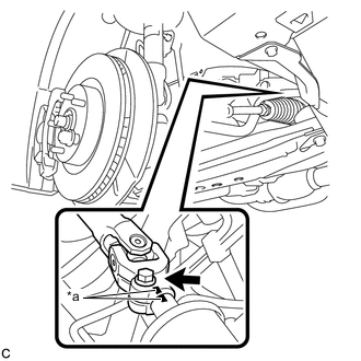
Connect the tie rod assembly LH to the steering knuckle with the nut.
49 N*m 500 kgf*cm 36 ft.*lbf -
Install a new cotter pin.
Note:Further tighten the nut up to 60° if the holes for the cotter pin are not aligned.
-
- Click here
CONNECT TIE ROD ASSEMBLY RH
Tip:Perform the same procedure as for the LH side.
- Click here
CONNECT STEERING INTERMEDIATE SHAFT ASSEMBLY
-
Align the matchmarks and install the steering intermediate shaft to the steering link assembly.
Table 2. Text in Illustration *a Matchmark -
Install a new bolt.
35 N*m 360 kgf*cm 26 ft.*lbf
-
- Click here
INSTALL FRONT WHEELS
103 N*m 1049 kgf*cm 76 ft.*lbf - Click here
INSPECT AND ADJUST FRONT WHEEL ALIGNMENT
- Click here
INSPECT STEERING WHEEL CENTER POINT