STEERING COLUMN ASSEMBLY INSTALLATION
PROCEDURE
-
INSTALL STEERING INTERMEDIATE SHAFT ASSEMBLY
-
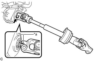
Text in Illustration *a Matchmark Install the steering intermediate shaft assembly to the steering column assembly.
Note
Align the matchmarks on the steering intermediate shaft assembly and the steering column assembly.
-
Install a new bolt.
- Torque:
- 35 N*m { 360 kgf*cm, 26 ft.*lbf }
-
-
INSTALL STEERING POST ASSEMBLY
-
Install the steering post assembly with the 4 nuts.
- Torque:
- 25 N*m { 255 kgf*cm, 18 ft.*lbf }
-
Install the ground wire with the bolt.
- Torque:
- 8.4 N*m { 85 kgf*cm, 74 in.*lbf }
-
Engage the clamp.
-
Connect the 2 connectors.
-
Connect the connectors and engage the wire harness clamps to the steering post assembly.
-
-
INSTALL NO. 2 AIR DUCT SUB-ASSEMBLY (for LHD)
-
Engage the 2 claws and guide to install the No. 2 air duct sub-assembly.
-
-
INSTALL NO. 2 AIR DUCT SUB-ASSEMBLY (for RHD)
-
Engage the 2 claws to install the No. 2 air duct sub-assembly.
-
Install the bolt.
- Torque:
- 9.8 N*m { 100 kgf*cm, 87 in.*lbf }
-
-
CONNECT STEERING INTERMEDIATE SHAFT ASSEMBLY
-
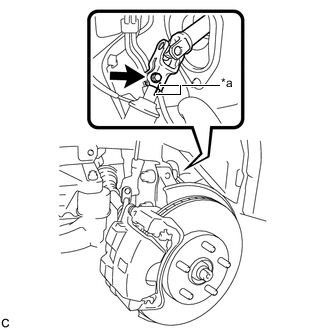
Text in Illustration *a Matchmark Connect the steering intermediate shaft assembly to the steering link assembly.
Note
Align the matchmarks on the steering intermediate shaft assembly and the steering link assembly.
-
Install a new bolt.
- Torque:
- 35 N*m { 360 kgf*cm, 26 ft.*lbf }
-
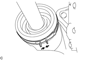
Tighten the clamp.
-
-
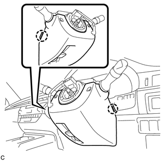
INSTALL TURN SIGNAL SWITCH ASSEMBLY WITH SPIRAL CABLE SUB-ASSEMBLY
Note
-
Do not replace the spiral cable with sensor sub-assembly with the auxiliary battery connected and the power switch on (IG).
-
Do not rotate the spiral cable with sensor sub-assembly without the steering wheel with the auxiliary battery connected and the power switch on (IG).
-
Ensure that the steering wheel is installed and aligned straight when inspecting the steering sensor.
-
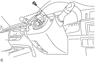
Engage the 3 claws to install the turn signal switch assembly with spiral cable sub-assembly to the steering post assembly.
-
Connect the connectors to the turn signal switch assembly with spiral cable sub-assembly.
-
-
INSTALL UPPER STEERING COLUMN COVER
-
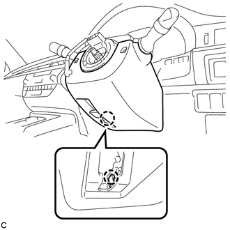
Engage the 2 claws to install the upper steering column cover.
-
Engage the 4 clips and 2 guides to the upper steering column cover.
-
-
INSTALL LOWER STEERING COLUMN COVER (for Manual Tilt and Manual Telescopic Steering Column)
-
Engage the 2 claws to install the lower steering column cover.
-
Install the 2 screws.
- Torque:
- 2.0 N*m { 20 kgf*cm, 18 in.*lbf }
-
Engage the claw.
-
-
INSTALL LOWER STEERING COLUMN COVER (for Power Tilt and Power Telescopic Steering Column)
-
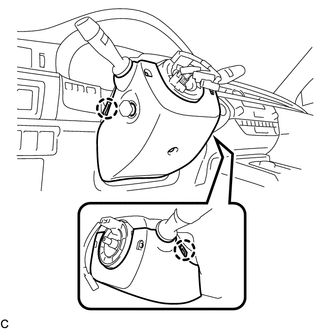
Engage the 2 claws to install the lower steering column cover.
-
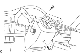
Install the 3 screws.
- Torque:
- 2.0 N*m { 20 kgf*cm, 18 in.*lbf }
-
-
INSTALL LOWER NO. 1 INSTRUMENT PANEL AIRBAG ASSEMBLY
-
TURN FRONT WHEELS TO FACE STRAIGHT AHEAD
-
INSPECT AND ADJUST SPIRAL CABLE WITH SENSOR SUB-ASSEMBLY
-
INSTALL STEERING WHEEL ASSEMBLY
-
INSPECT STEERING WHEEL CENTER POINT
-
INSTALL HORN BUTTON ASSEMBLY
-
INSTALL FRONT WHEEL
- Torque:
- 103 N*m { 1049 kgf*cm, 76 ft.*lbf }
-
CONNECT CABLE TO NEGATIVE AUXILIARY BATTERY TERMINAL (for Power Tilt and Power Telescopic Steering Column)
Note
-
When disconnecting the cable, some systems need to be initialized after the cable is reconnected Click here.
-
Connect the cable to the negative (-) auxiliary battery terminal with the front wheels facing straight ahead Click here.
-
Reset the auto tilt away function setting to the previous condition by changing the customize parameter Click here.
-
-
TORQUE SENSOR ZERO POINT CALIBRATION
-
ADJUST PARKING ASSIST MONITOR SYSTEM (w/ Parking Assist Monitor System)
w/ Parallel Parking Assist Function: Click here
w/o Parallel Parking Assist Function: Click here