REAR BRAKE REMOVAL

CAUTION / NOTICE / HINT
Note
-
When the brake pedal is first depressed after replacing the brake pads or pushing back the disc brake piston, DTC C1214 may be output. As there is no malfunction, clear the DTC.
-
While the auxiliary battery is connected, even if the power switch is off, the brake control system activates when the brake pedal is depressed or the door courtesy switch is turned on. Therefore, even if only brake pads are to be removed and installed, be sure to perform the Disable Brake Control procedure and disconnect the cable from the negative (-) terminal of the auxiliary battery before beginning work.
Tech Tips
-
Use the same procedure for the LH side and RH side.
-
The following procedure is for the LH side.
PROCEDURE
-
PRECAUTION
Note
After turning the power switch off, waiting time may be required before disconnecting the cable from the negative (-) auxiliary battery terminal. Therefore, make sure to read the disconnecting the cable from the negative (-) auxiliary battery terminal notice before proceeding with work Click here.
-
DISABLE BRAKE CONTROL (for LHD)
-
REMOVE WINDSHIELD WIPER MOTOR AND LINK ASSEMBLY (for RHD)
Tech Tips
Use the same procedure as for LHD Click here.
-
REMOVE FRONT OUTER COWL TOP PANEL SUB-ASSEMBLY (for RHD)
-
DISABLE BRAKE CONTROL (for RHD)
-
REMOVE REAR WHEEL
-
DRAIN BRAKE FLUID
Note
If brake fluid leaks onto any painted surface, immediately wash it off.
-
SEPARATE REAR FLEXIBLE HOSE
-
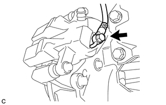
Remove the union bolt and gasket, and separate the rear flexible hose from the rear disc brake cylinder assembly.
-
-
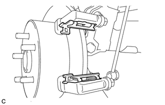
REMOVE REAR DISC BRAKE CYLINDER ASSEMBLY
-
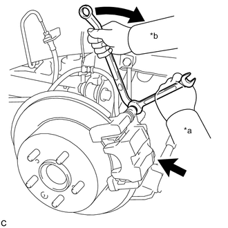
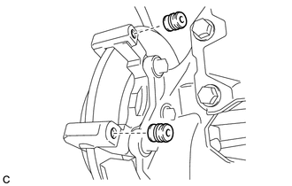
Text in Illustration *a Hold *b Turn Hold the rear disc brake cylinder slide pin, and remove the 2 bolts and rear disc brake cylinder assembly.
-
-
REMOVE REAR DISC BRAKE PAD
-
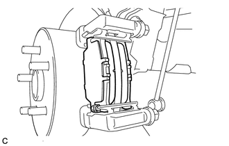
Remove the 2 rear disc brake pads with rear disc brake anti-squeal shim kit from the disc brake cylinder mounting.
-
-
REMOVE REAR DISC BRAKE ANTI-SQUEAL SHIM KIT
-
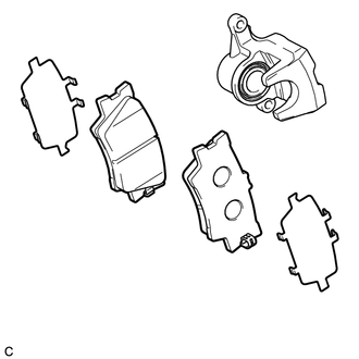
Remove the rear disc brake anti-squeal shim from each rear disc brake pad.
-
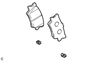
Remove the rear disc brake pad wear indicator plate from each rear disc brake pad.
-
-
REMOVE REAR DISC BRAKE PAD SUPPORT PLATE
-
Remove the 2 rear disc brake pad support plates from the disc brake cylinder mounting.
-
-
REMOVE REAR DISC BRAKE CYLINDER SLIDE PIN (for Upper Side)
-
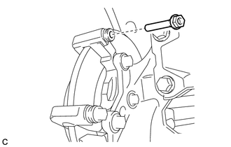
Remove the rear disc brake cylinder slide pin from the disc brake cylinder mounting.
-
-
REMOVE REAR DISC BRAKE CYLINDER SLIDE PIN (for Lower Side)
-
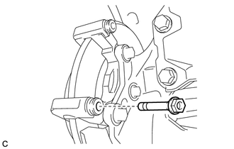
Remove the rear disc brake cylinder slide pin from the disc brake cylinder mounting.
-
-
REMOVE REAR DISC BRAKE CYLINDER SLIDE BUSHING
-
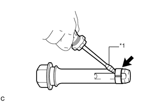
Text in Illustration *1 Protective Tape Using a screwdriver with its tip wrapped with protective tape, remove the rear disc brake cylinder slide bushing from the rear disc brake cylinder slide pin.
Note
Do not damage the rear disc brake cylinder slide pin.
-
-
REMOVE REAR DISC BRAKE BUSHING DUST BOOT
-
Remove the 2 rear disc brake bushing dust boots from the disc brake cylinder mounting.
-
-
REMOVE DISC BRAKE CYLINDER MOUNTING
-
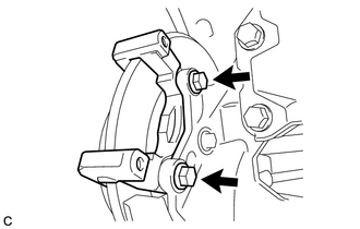
Remove the 2 bolts and disc brake cylinder mounting.
-
-
REMOVE PARKING BRAKE SHOE ADJUSTING HOLE PLUG
-
Remove the parking brake shoe adjusting hole plug.
-
-
REMOVE REAR DISC
-
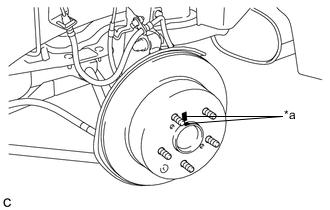
Text in Illustration *a Matchmark Put matchmarks on the rear disc and the rear axle hub.
-
Release the parking brake and remove the rear disc.
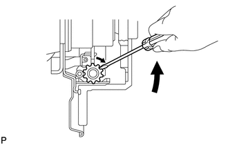
Tech Tips
If the disc cannot be removed easily, use a screwdriver to turn the shoe adjuster as shown in the illustration in order to contract the parking brake shoes.
-