PROCEDURE
- Click here
PRECAUTION
Note:After turning the power switch off, waiting time may be required before disconnecting the cable from the negative (-) auxiliary battery terminal. Therefore, make sure to read the disconnecting the cable from the negative (-) auxiliary battery terminal notices before proceeding with work (Click here).
- Click here
RECOVER REFRIGERANT FROM REFRIGERATION SYSTEM
- Click here
DISABLE BRAKE CONTROL
- Click here
REMOVE WINDSHIELD WIPER MOTOR AND LINK ASSEMBLY
- Click here
REMOVE FRONT OUTER COWL TOP PANEL SUB-ASSEMBLY
- Click here
REMOVE COOL AIR INTAKE DUCT SEAL
- Click here
REMOVE INLET AIR CLEANER ASSEMBLY
- Click here
REMOVE AIR CLEANER CAP SUB-ASSEMBLY
- Click here
REMOVE AIR CLEANER FILTER ELEMENT SUB-ASSEMBLY
- Click here
REMOVE AIR CLEANER CASE SUB-ASSEMBLY
- Click here
SEPARATE AIR CONDITIONER TUBE AND ACCESSORY ASSEMBLY
-
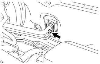
Remove the bolt from the hook connector.
-
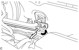
Turn the hook connector and separate the air conditioning tube and accessory assembly from the air conditioning unit.
Note:
-
Do not deform the piping.
-
Do not damage the plastic clamp.
-
-
Remove the O-ring from the air conditioning tube and accessory assembly.
Note:Seal the openings of the disconnected parts using vinyl tape to prevent entry of moisture and foreign matter.
-
- Click here
SEPARATE SUCTION PIPE SUB-ASSEMBLY
-
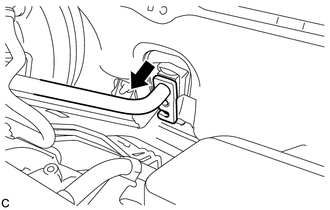
Separate the suction pipe sub-assembly from the air conditioning unit.
Note:
-
Do not deform the piping.
-
Do not damage the plastic clamp.
-
-
Remove the O-ring from the suction pipe sub-assembly.
Note:Seal the openings of the disconnected parts using vinyl tape to prevent entry of moisture and foreign matter.
-
- Click here
DRAIN BRAKE FLUID
Note:If brake fluid leaks onto any painted surface, immediately clean it off.
- Click here
SEPARATE BRAKE MASTER CYLINDER RESERVOIR ASSEMBLY
- Click here
SEPARATE NO. 1 BRAKE ACTUATOR TUBE
- Click here
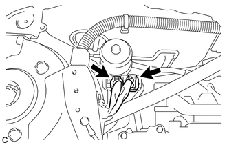
DISCONNECT NO. 2 BRAKE ACTUATOR HOSE
-
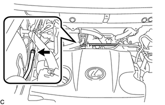
Move the clip and disconnect the No. 2 brake actuator hose from the No. 1 brake actuator tube.
-
- Click here
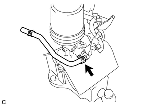
DISCONNECT FRONT NO. 1 BRAKE TUBE
-
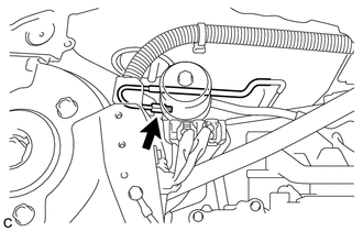
Using a union nut wrench, disconnect the front No. 1 brake tube from the brake booster pump assembly.
-
- Click here
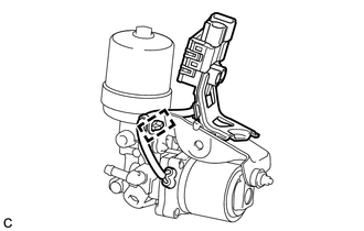
REMOVE BRAKE BOOSTER PUMP ASSEMBLY WITH BRACKET
-
Disconnect the 2 connectors from the brake booster pump assembly.
-
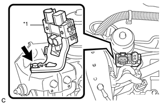
Remove the bolt and separate the connector box of the brake booster pump assembly from the brake actuator bracket assembly.
Table 1. Text in Illustration *1 Connector Box -
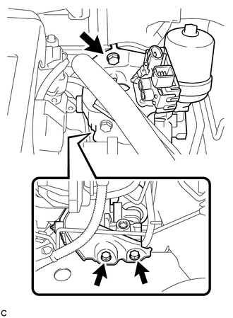
Remove the 3 bolts and brake booster pump assembly with bracket from the vehicle body.
Note:Do not kink or damage the brake line, suction pipe sub-assembly or air conditioning tube and accessory assembly.
-
- Click here
REMOVE NO. 2 BRAKE ACTUATOR HOSE
-
Move the clip and remove the No. 2 brake actuator hose from the brake booster pump assembly.
-
- Click here
REMOVE BRAKE BOOSTER PUMP ASSEMBLY
-
Disengage the wire harness clamp from the brake actuator bracket assembly.
-
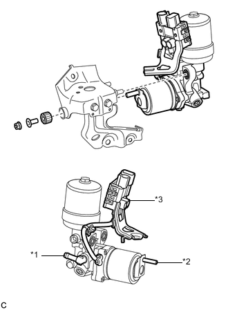
Remove the nut, brake actuator case collar, brake booster pump bushing and brake booster pump assembly from the brake actuator bracket assembly.
Table 2. Text in Illustration *1 Union *2 Stud *3 Connector Box and Wire Harness Note:
-
Do not carry the brake booster pump assembly by the parts shown in bold (*1, *2 and *3) in the illustration.
-
Do not drop the brake booster pump assembly when carrying it.
-
Be careful not to allow any brake fluid to enter the connector.
-
-
- Click here
INSTALL BRAKE BOOSTER PUMP ASSEMBLY