НАГНЕТАЮЩИЙ ТОПЛИВНЫЙ НАСОС СНЯТИЕ
Note
-
When replacing the injectors (including shuffling the injectors between the cylinders), common rail, intake manifold or cylinder head, it is necessary to replace the injection pipes with new ones.
-
When replacing the fuel supply pump, common rail, intake manifold or cylinder head, it is necessary to replace the fuel inlet pipe with a new one.
-
PRECAUTION
Note
After turning the ignition switch off, waiting time may be required before disconnecting the cable from the battery terminal. Therefore, make sure to read the disconnecting the cable from the battery terminal notice before proceeding with work Click here.
-
DISCONNECT CABLE FROM NEGATIVE BATTERY TERMINAL
Note
When disconnecting the cable, some systems need to be initialized after the cable is reconnected Click here.
-
REMOVE NO. 1 ENGINE COVER
-
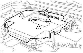
Возьмитесь сзади за крышку двигателя № 1 и медленно поднимите ее, чтобы разъединить задний фиксатор крышки двигателя № 1. Продолжайте поднимать крышку двигателя № 1, чтобы освободить 3 передних и боковых фиксатора крышки двигателя № 1, после чего снимите крышку двигателя № 1.
Note
Попытка освободить задний и передние фиксаторы за один прием может привести к поломке крышки.
-
-
REMOVE AIR CLEANER CAP SUB-ASSEMBLY
-
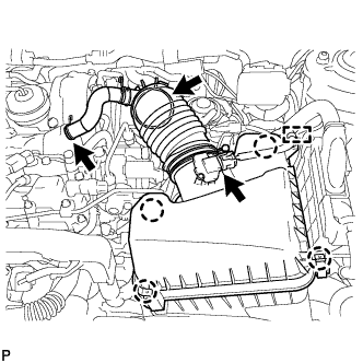
Открепите зажим и отсоедините разъем датчика массового расхода воздуха.
-
Сдвиньте хомут и отсоедините шланг системы принудительной вентиляции картера от крышки головки блока цилиндров.
-
Сдвиньте хомут и отсоедините шланг воздушного фильтра в сборе от турбонагнетателя.
-
Освободите 4 зажима и снимите крышку воздушного фильтра в сборе.
-
-
REMOVE AIR CLEANER FILTER ELEMENT SUB-ASSEMBLY
-
REMOVE AIR CLEANER CASE SUB-ASSEMBLY
-
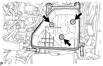
Выверните 3 болта и снимите корпус воздушного фильтра.
-
-
REMOVE NO. 3 FUEL HOSE
-
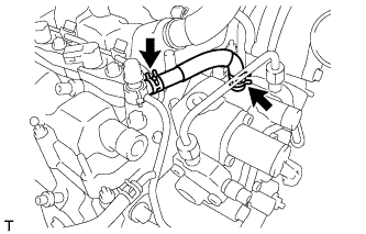
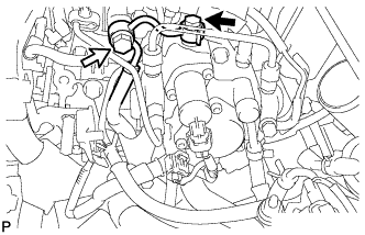
Using pliers, grip the claws of the 2 clips and slide the 2 clips to remove the No. 3 fuel hose from the supply pump assembly and No. 1 nozzle leakage pipe.
-
-
REMOVE NO. 1 FUEL HOSE
-
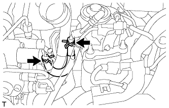
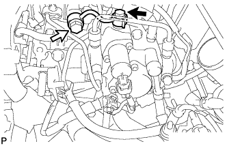
Using pliers, grip the claws of the 2 clips and slide the 2 clips to remove the No. 1 fuel hose from the supply pump assembly and fuel filter assembly.
-
-
REMOVE FUEL INLET PIPE SUB-ASSEMBLY
Note
After removing the fuel inlet pipe, cover the common rail and supply pump with electrical tape to prevent dirt from entering them.
-
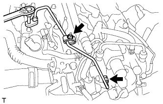
Remove the nut and 2 No. 2 injection pipe clamps.
-
Using a 14 mm union nut wrench, remove the fuel inlet pipe sub-assembly.
-
-
REMOVE FUEL HOSE PROTECTOR (for DPF)
-
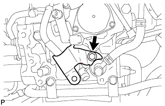
Remove the bolt and fuel hose protector.
-
-
REMOVE FUEL TUBE SUB-ASSEMBLY (for DPF)
-
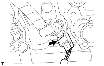
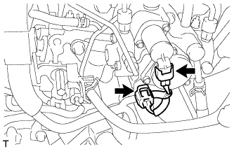
Disconnect the exhaust fuel addition injector connector.
-
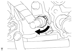
Turn the retainer as shown in the illustration.
-
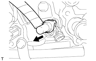
Disconnect the fuel tube sub-assembly from the exhaust fuel addition injector assembly.
-
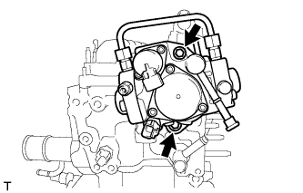
Remove the check valve and gasket.
Text in Illustration 
Check Valve -
Remove the union bolt, gasket and fuel tube sub-assembly.
-
-
REMOVE NO. 2 FUEL PIPE (for CCo)
-
Remove the check valve and gasket.
Text in Illustration Check Valve -
Remove the union bolt, gasket and No. 2 fuel pipe.
-
-
REMOVE FUEL SUPPLY PUMP ASSEMBLY
-
Disconnect the fuel temperature sensor connector.
-
Disconnect the suction control valve connector.
-
Remove the 2 bolts, fuel supply pump assembly and supply pump drive coupling.
-
Remove the O-ring from the fuel supply pump assembly.
-