ЗАДНИЙ САЛЬНИК КОЛЕНЧАТОГО ВАЛА УСТАНОВКА

-
INSTALL REAR CRANKSHAFT OIL SEAL
-
Apply MP grease to the lip of a new rear crankshaft oil seal.
-
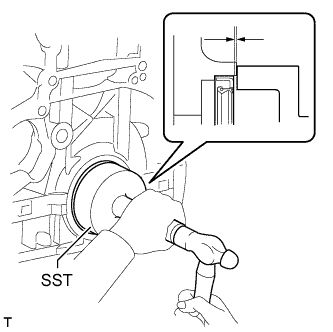
Using SST and a hammer, tap in the rear crankshaft oil seal as shown in the illustration.
- SST
- 09223-56010
Standard depth 0 to 0.9 mm (0 to 0.0354 in.) Note
-
Keep the lip free from foreign matter.
-
Do not tap the rear crankshaft oil seal at an angle.
-
Make sure that the rear crankshaft oil seal is properly installed.
-
-
INSTALL FLYWHEEL SUB-ASSEMBLY
-
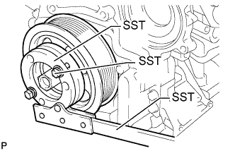
Удерживайте шкив коленчатого вала с помощью SST.
- SST
- 09213-58014 ( 91551-80840 )
- 09330-00021
-
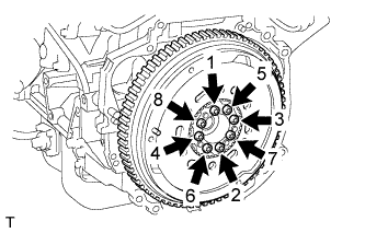
Используя торцевой ключ с головкой "TORX" T55, закрепите маховик 8 новыми болтами и равномерно в несколько этапов затяните болты в последовательности, показанной на рисунке.
- Torque:
- 71 Н*м { 720 кгс*см, 52 фунт-сила-фута }
Note
-
Повторное использование установочных болтов маховика не допускается.
-
Обязательно проверьте момент затяжки в течение 5 минут после затягивания.
-
Не ударьте и не повредите установочные болты маховика. Обращайтесь с ними осторожно.
-
Убедитесь в отсутствии масла на болтах.
Tech Tips
Убедитесь, что на посадочной поверхности установочных болтов маховика и установочных поверхностях коленчатого вала и маховика нет масла и посторонних веществ.
-
-
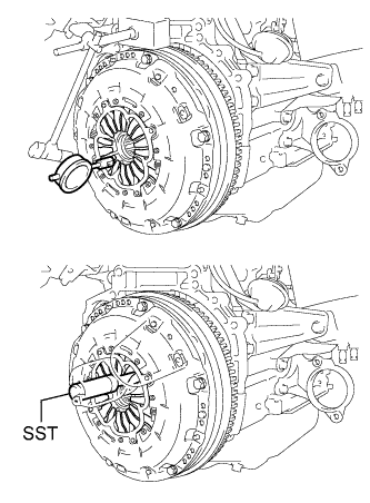
INSTALL CLUTCH DISC ASSEMBLY
-
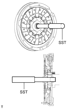
Insert SST into the clutch disc, and then insert them into the flywheel.
- SST
- 09301-00310
Note
Insert the clutch disc with the disc facing in the correct direction.
-
-
INSTALL CLUTCH COVER ASSEMBLY
-
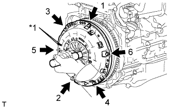
Text in Illustration *1 Matchmark Align the matchmark on the clutch cover with the one on the flywheel.
-
Install and tighten the 6 bolts uniformly in the order shown in the illustration, starting with the bolt located near the knock pin on the top.
- Torque:
- 19 N*m { 195 kgf*cm, 14 ft.*lbf }
Note
-
Be sure to uniformly tighten the bolts 180° at a time according to the order in the illustration.
-
Move SST up and down, right and left lightly after checking that the clutch disc assembly is in the center, and then tighten the bolts.
-
-
INSPECT AND ADJUST CLUTCH COVER ASSEMBLY
-
Using a dial indicator with a roller instrument, measure the diaphragm spring tip alignment.
Maximum misalignment 1.3 mm (0.0512 in.) If the misalignment is more than the maximum, using SST, adjust the diaphragm spring tip alignment.
- SST
- 09333-00013
-
-
INSTALL MANUAL TRANSAXLE ASSEMBLY
-
CONNECT CABLE TO NEGATIVE BATTERY TERMINAL
Note
When disconnecting the cable, some systems need to be initialized after the cable is reconnected Click here.