СИСТЕМА ECD (для CCo), Diagnostic DTC:P0234, P0299, P1251
| DTC Code | DTC Name |
|---|---|
| P0234 | Turbocharger / Supercharger Overboost Condition |
| P0299 | Turbocharger / Supercharger Underboost |
| P1251 | Turbocharger / Supercharger Overboost Condition (Too High) |
DESCRIPTION
| DTC Detection Drive Pattern | DTC Detection Condition | Trouble Area |
|---|---|---|
| After warming up the engine, the vehicle is driven at a constant vehicle speed at an engine speed of 2400 rpm or more for 2 minutes | Actual turbocharger pressure "MAP" deviates by 30 kPa (225 mmHg, 8.9 in.Hg) or higher from the simulated target pressure "Target Booster Pressure" for 100 seconds at an engine speed of 2400 to 4000 rpm. (1 trip detection logic) |
|
| DTC Detection Drive Pattern | DTC Detection Condition | Trouble Area |
|---|---|---|
| After warming up the engine, the vehicle is driven at a constant vehicle speed at an engine speed of 2400 rpm or more for 2 minutes | When any condition below is met (2 trip detection logic):
|
|
| DTC Detection Drive Pattern | DTC Detection Condition | Trouble Area |
|---|---|---|
| After warming up the engine, fully depress the accelerator pedal for 5 seconds or more so that the engine speed is 2400 rpm or more. | The turbocharger pressure is 300 kPa (2250 mmHg, 89 in.Hg) or more for 5 seconds or more at an engine speed of 2000 to 4000 rpm. (1 trip detection logic) |
|
| DTC No. | Data List |
|---|---|
| P0234 |
|
| P0299 | |
| P1251 |
WIRING DIAGRAM
Refer to DTC P0045 Click here.
INSPECTION PROCEDURE
Note
-
Inspect the fuses of circuits related to this system before performing the following inspection procedure.
-
After replacing the ECM, the new ECM needs registration Click here and initialization Click here.
PROCEDURE
-
READ OUTPUT DTC (RECORD STORED DTC AND FREEZE FRAME DATA)
-
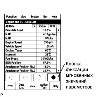
Connect the intelligent tester to the DLC3.
-
Turn the ignition switch to ON and turn the tester on.
-
Enter the following menus: Powertrain / Engine and ECT / DTC.
-
Record the stored DTC and Freeze Frame Data.
Tech Tips
Be sure to carefully examine "MAP" and "Target Booster Pressure" in the freeze frame data.
NEXT 
-
-
CHECK ANY OTHER DTCS OUTPUT (IN ADDITION TO DTC P0234, P0299 AND/OR P1251)
-
Connect the intelligent tester to the DLC3.
-
Turn the ignition switch to ON and turn the tester on.
-
Enter the following menus: Powertrain / Engine and ECT / DTC.
-
Read the DTCs.
Result Result Proceed to P0234, P0299 and/or P1251 A P0234, P0299 and/or P1251 and other DTCs B
B 
GO TO DTC CHART Click here
A
-
-
READ VALUE USING INTELLIGENT TESTER (MAP AND TARGET BOOSTER PRESSURE)
-
Connect the intelligent tester to the DLC3.
-
Start the engine and turn the tester on.
-
Enter the following menus: Powertrain / Engine and ECT / Data List / MAP and Target Booster Pressure.
-
Take a snapshot when the engine speed is maintained at 4500 rpm with no load.
-
Read the values of "MAP" and "Target Booster Pressure" in the Data List using the snapshot review function.
Result Result Proceed to Difference between MAP and Target Booster Pressure is +/-15 kPa or higher A Except above B
B 
CONFIRM WHETHER MALFUNCTION HAS BEEN SUCCESSFULLY REPAIRED Click here
A
-
-
CHECK AIR INTAKE SYSTEM
-
Check for air leaks and blockages between the air cleaner case and turbocharger, and between turbocharger and intake manifold.
Result Result Proceed to Leaks and/or blockages exist in the intake system A No leaks and/or blockages in the intake system B Tech Tips
-
Inspect the air intake system, especially hoses and pipes between the air cleaner and turbocharger.
-
Check for abnormal disconnections, pipe and hose squashing, and any damage in the intake system.
-
Using your hand, check whether the pipes and hoses in the intake system are securely connected.
-
By applying soapy water and revving up the engine, air leaks from the intake system can be checked by checking for bubbles.
-
Check for any modifications in the intake system made by the user.
-
Check if the vacuum hose for the manifold absolute pressure sensor is disconnected.
-
B
CHECK CONNECTION OF VACUUM HOSE Click here
A
-
-
REPAIR OR REPLACE AIR INTAKE SYSTEM
NEXT
-
READ VALUE USING INTELLIGENT TESTER (MAP AND TARGET BOOSTER PRESSURE)
-
Connect the intelligent tester to the DLC3.
-
Start the engine and turn the tester on.
-
Enter the following menus: Powertrain / Engine and ECT / Data List / MAP and Target Booster Pressure.
-
Take a snapshot when the engine speed is maintained at 4500 rpm with no load.
-
Read the values of "MAP" and "Target Booster Pressure" in the Data List using the snapshot review function.
Result Result Proceed to Difference between MAP and Target Booster Pressure is +/-15 kPa or higher A Except above B
B
CONFIRM WHETHER MALFUNCTION HAS BEEN SUCCESSFULLY REPAIRED Click here
A
-
-
CHECK CONNECTION OF VACUUM HOSE
-
Check the turbocharger system vacuum hose connections
NG
REPAIR OR REPLACE VACUUM HOSE Click here
OK
-
-
INSPECT E-VRV FOR TURBOCHARGER CONTROL (E-VRV RESISTANCE)
-
Inspect the E-VRV Click here.
NG
REPLACE E-VRV FOR TURBOCHARGER CONTROL Click here
OK
-
-
CHECK TURBOCHARGER SUB-ASSEMBLY
-
Check the turbocharger sub-assembly Click here.
NG
REPLACE TURBOCHARGER SUB-ASSEMBLY Click here
OK
-
-
CHECK HARNESS AND CONNECTOR (E-VRV FOR TURBOCHARGER CONTROL - ECM)
-
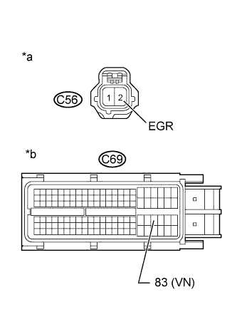
Text in Illustration *a Front view of wire harness connector
(to E-VRV)
*b Front view of wire harness connector
(to ECM)
Disconnect the E-VRV connector.
-
Disconnect the ECM connector.
-
Measure the resistance according to the value(s) in the table below.
Standard Resistance (Check for Open) Tester Connection Condition Specified Condition C56-2 (EGR) - C69-83 (VN) Always Below 1 Ω Standard Resistance (Check for Short) Tester Connection Condition Specified Condition C56-2 (EGR) or C69-83 (VN) - Body ground Always 10 kΩ or higher -
Reconnect the E-VRV connector.
-
Reconnect the ECM connector.
NG
REPAIR OR REPLACE HARNESS OR CONNECTOR Click here
OK
-
-
CHECK DIESEL THROTTLE BODY ASSEMBLY
-
Connect the intelligent tester to the DLC3.
-
Start the engine and turn the tester on.
-
Enter the following menus: Powertrain / Engine and ECT / Data List / Actual Throttle Position.
-
Take a snapshot when accelerating with the accelerator fully depressed.
-
Read the value of "Actual Throttle Position" in the Data List using the snapshot review function.
Result The value for "Actual Throttle Position" is 0%.
NG
REPLACE DIESEL THROTTLE BODY ASSEMBLY Click here
OK
-
-
CHECK EGR VALVE ASSEMBLY
-
Connect the intelligent tester to the DLC3.
-
Start the engine and turn the tester on.
-
Enter the following menus: Powertrain / Engine and ECT / Data List / Actual EGR Valve Pos..
-
Take a snapshot when accelerating with the accelerator fully depressed.
-
Read the value of "Actual EGR Valve Pos." in the Data List using the snapshot review function.
Result The value for "Actual EGR Valve Pos." is 0%.
NG
REPLACE EGR VALVE ASSEMBLY Click here
OK
-
-
READ VALUE USING INTELLIGENT TESTER (INJECTION FEEDBACK VAL #1 TO #4)
-
Connect the intelligent tester to the DLC3.
-
Turn the ignition switch to ON and turn the tester on.
-
Start the engine and warm it up.
-
Enter the following menus: Powertrain / Engine and ECT / Data List / Injection Feedback Val #1 to #4.
-
Read the values.
Standard Value Item Engine Speed* Reference Value Injection Feedback Val #1 to #4 Idling -3.0 to 3.0 mm3/st
Tech Tips
-
*: The A/C switch and all accessory switches should be off, and the engine should be fully warmed up.
-
When the values are outside the standard range, deposits inside the fuel injectors may be causing the problem.
OK Values are within the standard range. -
NG
REPLACE FUEL INJECTOR OF MALFUNCTIONING CYLINDER Click here
OK
-
-
CHECK ANY OTHER DTCS OUTPUT (IN ADDITION TO DTC P0234, P0299 AND/OR P1251)
-
Connect the intelligent tester to the DLC3.
-
Clear the DTCs Click here.
-
Turn the ignition switch off for 30 seconds or more.
-
Start the engine and warm it up for 1 minute or more.
-
Turn the tester on.
-
Read the value of Engine Speed from the Freeze Frame Data recorded previously.
Tech Tips
When performing the DTC detection drive pattern, make sure the engine speed increases to 2400 rpm or more and exceeds the "Engine Speed" value from the freeze frame data.
-
After warming up the engine, drive the vehicle at a constant vehicle speed at an engine speed of 2400 rpm or more for 2 minutes.
-
With the engine warmed up, fully depress the accelerator pedal for 5 seconds or more so that the engine speed is 2400 rpm or more.
-
Enter the following menus: Powertrain / Engine and ECT / DTC / Pending.
-
Read the DTC.
Result Result Proceed to No output A P0234, P0299 and/or P1251 B
B
REPLACE ECM Click here
A 
END
-
-
REPLACE FUEL INJECTOR OF MALFUNCTIONING CYLINDER
-
Replace the fuel injector Click here.
NEXT
-
-
BLEED AIR FROM FUEL SYSTEM
-
Bleed the air from the fuel system Click here.
NEXT
-
-
REGISTER INJECTOR COMPENSATION CODE AND PERFORM PILOT QUANTITY LEARNING
-
Register the injector compensation code Click here.
-
Perform the fuel injector pilot quantity learning Click here.
NEXT
CONFIRM WHETHER MALFUNCTION HAS BEEN SUCCESSFULLY REPAIRED Click here
-
-
REPAIR OR REPLACE VACUUM HOSE
-
Repair or replace the vacuum hose.
NEXT
CONFIRM WHETHER MALFUNCTION HAS BEEN SUCCESSFULLY REPAIRED Click here
-
-
REPLACE E-VRV FOR TURBOCHARGER CONTROL
-
Replace the E-VRV Click here.
NEXT
CONFIRM WHETHER MALFUNCTION HAS BEEN SUCCESSFULLY REPAIRED Click here
-
-
REPLACE TURBOCHARGER SUB-ASSEMBLY
-
Replace the turbocharger sub-assembly Click here.
NEXT
CONFIRM WHETHER MALFUNCTION HAS BEEN SUCCESSFULLY REPAIRED Click here
-
-
REPAIR OR REPLACE HARNESS OR CONNECTOR
-
Repair or replace the harness or connector.
NEXT
CONFIRM WHETHER MALFUNCTION HAS BEEN SUCCESSFULLY REPAIRED Click here
-
-
REPLACE DIESEL THROTTLE BODY ASSEMBLY
-
Replace the diesel throttle body assembly Click here.
NEXT
CONFIRM WHETHER MALFUNCTION HAS BEEN SUCCESSFULLY REPAIRED Click here
-
-
REPLACE EGR VALVE ASSEMBLY
-
Replace the EGR valve assembly Click here.
NEXT
CONFIRM WHETHER MALFUNCTION HAS BEEN SUCCESSFULLY REPAIRED Click here
-
-
REPLACE ECM
-
Replace the ECM Click here.
NEXT
-
-
CONFIRM WHETHER MALFUNCTION HAS BEEN SUCCESSFULLY REPAIRED
-
Connect the intelligent tester to the DLC3.
-
Clear the DTCs Click here.
-
Turn the ignition switch off for 30 seconds or more.
-
Start the engine and warm it up.
-
Turn the tester on.
-
Read the value of Engine Speed from the Freeze Frame Data recorded previously.
Tech Tips
When performing the DTC detection drive pattern, make sure the engine speed increases to 2400 rpm or more and exceeds the "Engine Speed" value from the freeze frame data.
-
After warming up the engine, drive the vehicle at a constant vehicle speed at an engine speed of 2400 rpm or more for 2 minutes.*A
-
With the engine warmed up, fully depress the accelerator pedal for 5 seconds or more so that the engine speed is 2400 rpm or more.*B
-
Confirm that the DTC is not output again.
Tech Tips
Perform the following procedure using the tester to determine whether or not the DTC judgment has been carried out.
-
Enter the following menus: Powertrain / Engine and ECT / Utility / All Readiness.
-
Input DTC P0234, P0299 and/or P1251.
-
Check that STATUS is NORMAL.
Tech Tips
-
If STATUS is NORMAL, DTC judgment is complete and the system is determined to be normal.
-
If STATUS is INCOMPLETE or UNKNOWN, perform *A and *B again.
-
-
NEXT
END
-