LANE DEPARTURE ALERT SYSTEM(w/o Dynamic Radar Cruise Control System) Indicator Circuit
DESCRIPTION
When the lane departure warning camera detects a lane departure alert main switch signal, it sends the signal to the combination meter assembly via CAN communication. Then the lane departure alert indicator turns on.
WIRING DIAGRAM
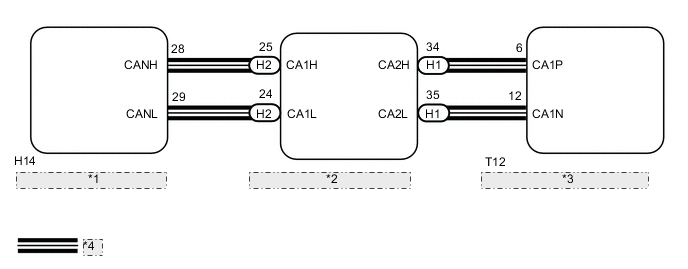
| *1 | Combination Meter Assembly |
| *2 | Power Management Control ECU |
| *3 | Lane Departure Warning Camera |
| *4 | CAN Communication Line |
PROCEDURE
-
READ VALUE USING GTS (CAN BUS CHECK)
-
Connect the GTS to the DLC3.
-
Turn the power switch on (IG).
-
Enter the following menus: System Select / Can Bus Check.
Result Result Proceed to All of the ECUs and sensors that are currently connected to the CAN communication system are displayed. A None of the ECUs and sensors that are currently connected to the CAN communication system are displayed, or some of them are not displayed. B -
Turn the power switch off.
B 
GO TO CAN COMMUNICATION SYSTEM Click here
A 
-
-
CHECK FOR DTCs (HEALTH CHECK)
-
Connect the GTS to the DLC3.
-
Turn the power switch on (IG).
-
Enter the following menus: System Select / Health Check.
-
Check DTCs.
Result Result Proceed to No DTCs are output. A DTCs are output. B -
Turn the power switch off.
B
GO TO DTC CHART
A
-
-
PERFORM ACTIVE TEST USING GTS (LDA CONTROL INDICATOR)
-
Connect the GTS to the DLC3.
-
Turn the power switch on (IG).
-
Enter the following menus: Body Electrical / Combination Meter / Active Test / LDA Control Indicator.
-
Perform the Active Test.
Combination Meter Tester Display Test Part Control Range Diagnostic Note LDA Control Indicator Lane departure alert indicator ON/OFF Confirm that the vehicle is stopped with the power switch on (IG). OK Lane departure alert indicator turns on/off. -
Turn the power switch off.
NG
REPLACE COMBINATION METER ASSEMBLY Click here
OK
-
-
READ VALUE USING GTS (LDA INDICATOR)
-
Connect the GTS to the DLC3.
-
Turn the power switch on (IG).
-
Enter the following menus: Chassis / Lane Departure Alert / Data List / LDA Indicator.
-
Read the value displayed on the GTS.
Lane Departure Alert Tester Display Measurement Item/Range Normal Condition Diagnostic Note LDA Indicator Status of the lane departure alert Indicator / Nothing or Green Nothing: Lane Departure Alert indicator is not illuminated
Green: Lane Departure Alert indicator is illuminated
- OK The value on the GTS and status of the lane departure alert indicator on the combination meter assembly are the same. -
Turn the power switch off.
OK
PROCEED TO NEXT SUSPECTED AREA SHOWN IN PROBLEM SYMPTOMS TABLE Click here
NG
REPLACE LANE DEPARTURE WARNING CAMERA Click here
-