REAR AXLE HUB BOLT REPLACEMENT

CAUTION / NOTICE / HINT
Note
When the brake pedal is first depressed after replacing the brake pads or pushing back the disc brake piston, DTC C1214 may be output. As there is no malfunction, clear the DTC.
Tech Tips
-
Use the same procedure for the RH side and LH side.
-
The procedure listed below is for the LH side.
PROCEDURE
-
PRECAUTION
Note
After turning the power switch off, waiting time may be required before disconnecting the cable from the negative (-) auxiliary battery terminal. Therefore, make sure to read the disconnecting the cable from the negative (-) auxiliary battery terminal notice before proceeding with work Click here.
-
DISABLE BRAKE CONTROL (for LHD)
-
REMOVE WINDSHIELD WIPER MOTOR AND LINK ASSEMBLY (for RHD)
Tech Tips
Use the same procedure as for LHD Click here.
-
REMOVE FRONT OUTER COWL TOP PANEL SUB-ASSEMBLY (for RHD)
-
DISABLE BRAKE CONTROL (for RHD)
-
REMOVE REAR WHEEL
-
SEPARATE REAR DISC BRAKE CALIPER ASSEMBLY
-
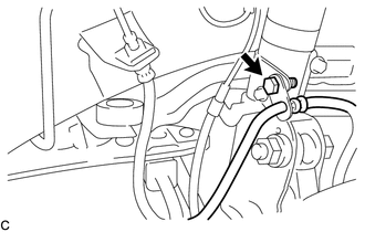
Remove the bolt and separate the rear flexible hose from the rear shock absorber.
-
Remove the 2 bolts, and separate the rear disc brake caliper assembly.
Note
Use wire or an equivalent tool to keep the rear disc brake caliper from hanging down by the flexible hose.
-
-
REMOVE PARKING BRAKE SHOE ADJUSTING HOLE PLUG
-
REMOVE REAR DISC
-
REMOVE REAR AXLE HUB BOLT
-
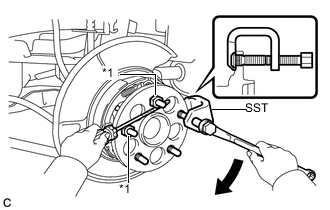
Text in Illustration *1 Service Nut Temporarily install 2 service nuts to the rear axle hub bolts as shown in the illustration.
Recommended service nut Thread diameter: 12.0 mm (0.472 in.) Thread pitch: 1.5 mm (0.0591 in.) Note
Install the service nuts to prevent damage to the rear axle hub bolts.
-
Using SST and a screwdriver or an equivalent tool to hold the rear axle hub and bearing assembly, remove the rear axle hub bolt.
- SST
- 09611-12010
Note
Do not damage the threads of the rear axle hub bolts.
-
-
INSTALL REAR AXLE HUB BOLT
-
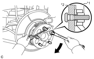
Text in Illustration *1 Service Nut *2 Washer Temporarily install a new rear axle hub bolt to the rear axle hub and bearing assembly.
-
Install a washer and service nut to the rear axle hub bolt as shown in the illustration.
Recommended service nut Thread diameter: 12.0 mm (0.472 in.) Thread pitch: 1.5 mm (0.0591 in.) Tech Tips
Recommended washer thickness is 5 mm (0.197 in.) or more.
-
Using a screwdriver or an equivalent tool to hold the rear axle hub and bearing assembly, install the rear axle hub bolt by tightening the service nut.
Note
-
Install the service nuts to prevent damage to the rear axle hub bolts.
-
Do not damage the threads of the rear axle hub bolts.
-
-
Remove the 3 service nuts and washer from the 3 rear axle hub bolts.
-
-
INSTALL REAR DISC
-
INSTALL PARKING BRAKE SHOE ADJUSTING HOLE PLUG
-
INSTALL REAR DISC BRAKE CALIPER ASSEMBLY
-
Install the rear disc brake caliper assembly with the 2 bolts.
- Torque:
- 78 N*m { 799 kgf*cm, 58 ft.*lbf }
-
Install the rear flexible hose to the rear shock absorber with the bolt.
- Torque:
- 19 N*m { 192 kgf*cm, 14 ft.*lbf }
-
-
CONNECT CABLE TO NEGATIVE AUXILIARY BATTERY TERMINAL
-
Connect the cable to the negative (-) auxiliary battery terminal Click here.
-
Connect the reservoir level switch connector.
-
Clear the DTCs Click here.
-
-
INSTALL FRONT OUTER COWL TOP PANEL SUB-ASSEMBLY (for RHD)
-
INSTALL WINDSHIELD WIPER MOTOR AND LINK ASSEMBLY (for RHD)
Tech Tips
Use the same procedure as for LHD Click here.
-
ADJUST PARKING BRAKE
-
INSTALL REAR WHEEL
- Torque:
- 103 N*m { 1049 kgf*cm, 76 ft.*lbf }