CAUTION / NOTICE / HINT
When the brake pedal is first depressed after replacing the brake pads or pushing back the disc brake piston, DTC C1214 may be output. As there is no malfunction, clear the DTC.
-
Use the same procedure for the RH side and LH side.
-
The procedure listed below is for the LH side.
PROCEDURE
- Click here
PRECAUTION
Note:After turning the power switch off, waiting time may be required before disconnecting the cable from the negative (-) auxiliary battery terminal. Therefore, make sure to read the disconnecting the cable from the negative (-) auxiliary battery terminal notice before proceeding with work (Click here).
- Click here
DISABLE BRAKE CONTROL (for LHD)
- Click here
REMOVE WINDSHIELD WIPER MOTOR AND LINK ASSEMBLY (for RHD)
Tip:Use the same procedure as for LHD (Click here).
- Click here
REMOVE FRONT OUTER COWL TOP PANEL SUB-ASSEMBLY (for RHD)
- Click here
DISABLE BRAKE CONTROL (for RHD)
- Click here
REMOVE FRONT WHEEL
- Click here
REMOVE FRONT AXLE SHAFT NUT
- Click here
SEPARATE FRONT SPEED SENSOR
-
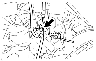
Remove the bolt, disengage the clamp and separate the front speed sensor and front flexible hose from the front shock absorber.
Note:Be sure to separate the front speed sensor from the front shock absorber completely.
-
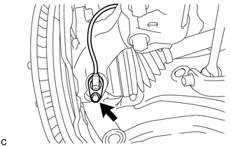
Remove the bolt and front speed sensor from the steering knuckle.
Note:
-
Prevent foreign matter from contacting the sensor tip.
-
Be careful not to damage the front speed sensor.
-
Clean the speed sensor installation hole and the contact surfaces every time the speed sensor is removed.
-
-
- Click here
SEPARATE FRONT DISC BRAKE CALIPER ASSEMBLY
- Click here
REMOVE FRONT DISC
- Click here
SEPARATE TIE ROD ASSEMBLY
- Click here
SEPARATE FRONT DRIVE SHAFT ASSEMBLY
-
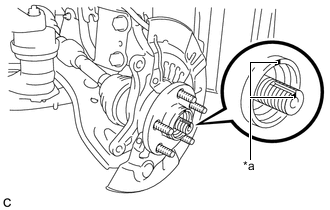
Put matchmarks on the front drive shaft assembly and the front axle hub sub-assembly.
Table 1. Text in Illustration *a Matchmark -
Using a plastic hammer, separate the front drive shaft assembly from the front axle assembly.
If it is difficult to separate, tap the end of the front drive shaft assembly using a brass bar and a hammer.
-
- Click here
SEPARATE FRONT LOWER NO. 1 SUSPENSION ARM SUB-ASSEMBLY
-
Remove the bolt and 2 nuts, and separate the front lower No. 1 suspension arm sub-assembly from the front lower ball joint assembly.
-
- Click here
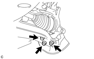
REMOVE FRONT AXLE ASSEMBLY
-
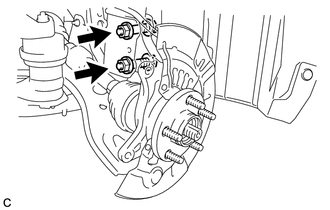
Remove the 2 bolts, 2 nuts and front axle assembly from the front shock absorber.
Note:
-
When removing the nuts, keep the bolts from rotating.
-
Be careful not to damage the drive shaft boot or speed sensor rotor.
-
-
- Click here
REMOVE FRONT NO. 1 WHEEL BEARING DUST DEFLECTOR
-
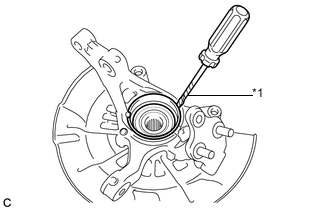
Using a screwdriver with its tip wrapped with protective tape, remove the front No. 1 wheel bearing dust deflector.
Table 2. Text in Illustration *1 Protective Tape Note:Be careful not to damage the steering knuckle.
-
- Click here
REMOVE FRONT AXLE HUB HOLE SNAP RING
-
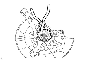
Using snap ring pliers, remove the front axle hub hole snap ring.
-
- Click here
REMOVE FRONT AXLE HUB SUB-ASSEMBLY
-
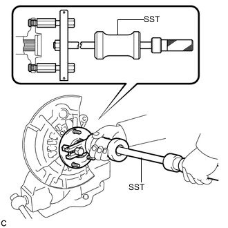
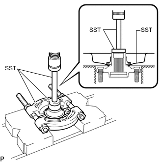
Hold the front axle assembly between aluminum plates in a vise.
Note:Do not overtighten the vise.
-
Using SST, remove the front axle hub sub-assembly.
09520-00031 -
Using SST and a press, remove the bearing inner race (outside) from the front axle hub sub-assembly.
09555-55010 09950-60010 09951-00440 09950-70010 09951-07100 Note:Be careful not to drop the front axle hub sub-assembly.
-
- Click here
REMOVE FRONT DISC BRAKE DUST COVER
-
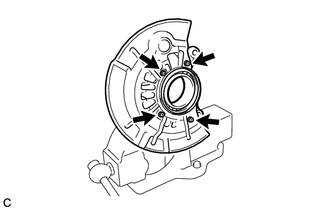
Remove the 4 bolts and front disc brake dust cover from the steering knuckle.
-
- Click here
REMOVE FRONT AXLE HUB BEARING
-
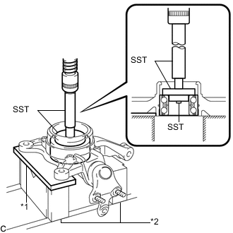
Place the bearing inner race (outside) on the front axle hub bearing.
Table 3. Text in Illustration *1 Steel Plate *2 V-block -
Using SST, a steel plate, V-blocks and a press, remove the front axle hub bearing from the steering knuckle.
09950-60010 09951-00440 09952-06010 09950-60020 09951-00750 09950-70010 09951-07100 Note:Keep the steering knuckle level.
-