PROCEDURE
- Click here
INSTALL FRONT DRIVE SHAFT ASSEMBLY LH
-
Coat the spline of the front drive inboard joint assembly with ATF.
-
Coat the lip of the hybrid vehicle transaxle assembly type T oil seal with MP grease.
-
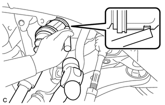
Align the inboard joint splines, and using a brass bar and a hammer, install the front drive shaft assembly LH.
Note:
-
Face the end gap of the front drive shaft hole snap ring LH downward.
-
Do not damage the hybrid vehicle transaxle assembly type T oil seal.
-
Do not damage the front axle inboard joint boot.
-
Make sure to center the front drive shaft assembly LH during installation to prevent damage to the front drive shaft hole snap ring LH.
Tip:Confirm whether the drive shaft is securely driven in by checking the reaction force and sound.
-
-
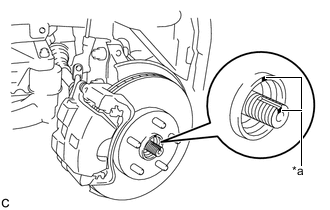
Align the matchmarks and install the front drive shaft assembly LH to the front axle hub sub-assembly.
Table 1. Text in Illustration *a Matchmark Note:Be careful not to damage the front axle outboard joint boot or speed sensor rotor.
-
- Click here
INSTALL FRONT DRIVE SHAFT ASSEMBLY RH
-
Coat the spline of the front drive inboard joint assembly with ATF.
-
Coat the lip of the hybrid vehicle transaxle assembly type T oil seal with MP grease.
-
Install a new bearing bracket hole snap ring to the front drive shaft assembly RH.
-
Install the front drive shaft assembly RH.
Note:
-
Do not damage the hybrid vehicle transaxle assembly type T oil seal.
-
Do not damage the front axle inboard joint boot.
-
When inserting the front drive shaft assembly RH, keep it level.
-
-
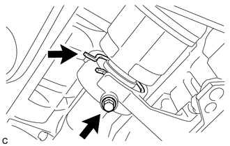
Install the bearing bracket hole snap ring and a new bolt.
32 N*m 330 kgf*cm 24 ft.*lbf -
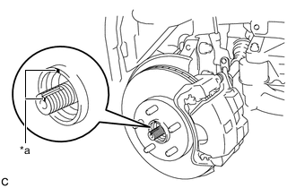
Align the matchmarks and install the front drive shaft assembly RH to the front axle hub sub-assembly.
Table 2. Text in Illustration *a Matchmark Note:Be careful not to damage the front axle outboard joint boot or speed sensor rotor.
-
- Click here
CONNECT FRONT LOWER NO. 1 SUSPENSION ARM SUB-ASSEMBLY
- Click here
CONNECT TIE ROD ASSEMBLY
- Click here
INSTALL FRONT SPEED SENSOR
- Click here
INSTALL FRONT STABILIZER LINK ASSEMBLY
- Click here
INSTALL FRONT AXLE SHAFT NUT
-
Clean the threaded parts on the front drive shaft assembly and a new front axle shaft nut using a non-residue solvent.
Note:
-
Be sure to perform this work even when using a new drive shaft.
-
Keep the threaded parts free of oil and foreign matter.
-
-
Using a socket wrench (30 mm), install the front axle shaft nut.
294 N*m 2998 kgf*cm 217 ft.*lbf Tip:Keep depressing the brake pedal to prevent the front drive shaft from rotating.
-
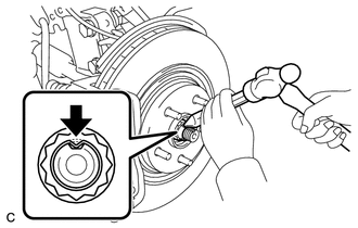
Using a chisel and hammer, stake the front axle shaft nut.
-
- Click here
INSTALL FRONT WHEELS
103 N*m 1049 kgf*cm 76 ft.*lbf - Click here
ADD HYBRID TRANSAXLE FLUID
- Click here
INSPECT HYBRID TRANSAXLE FLUID
- Click here
INSTALL FRONT FENDER APRON SEAL LH
- Click here
INSTALL FRONT FENDER APRON SEAL RH
- Click here
INSTALL ENGINE UNDER COVER LH
- Click here
INSTALL FRONT WHEEL OPENING EXTENSION PAD LH
- Click here
INSTALL ENGINE UNDER COVER RH
- Click here
INSTALL FRONT WHEEL OPENING EXTENSION PAD RH
- Click here
ADJUST FRONT WHEEL ALIGNMENT
- Click here
CHECK FOR SPEED SENSOR SIGNAL