REAR AXLE HUB ON-VEHICLE INSPECTION
CAUTION / NOTICE / HINT
Note
When the brake pedal is first depressed after replacing the brake pads or pushing back the disc brake piston, DTC C1214 may be output. As there is no malfunction, clear the DTC.
Tech Tips
-
Use the same procedure for the RH side and LH side.
-
The procedure listed below is for the LH side.
PROCEDURE
-
PRECAUTION
Note
After turning the power switch off, waiting time may be required before disconnecting the cable from the negative (-) auxiliary battery terminal. Therefore, make sure to read the disconnecting the cable from the negative (-) auxiliary battery terminal notice before proceeding with work Click here.
-
DISABLE BRAKE CONTROL (for LHD)
-
REMOVE WINDSHIELD WIPER MOTOR AND LINK ASSEMBLY (for RHD)
Tech Tips
Use the same procedure as for LHD Click here.
-
REMOVE FRONT OUTER COWL TOP PANEL SUB-ASSEMBLY (for RHD)
-
DISABLE BRAKE CONTROL (for RHD)
-
REMOVE REAR WHEEL
-
SEPARATE REAR DISC BRAKE CALIPER ASSEMBLY
-
REMOVE PARKING BRAKE SHOE ADJUSTING HOLE PLUG
-
REMOVE REAR DISC
-
INSPECT REAR AXLE HUB BEARING LOOSENESS
-
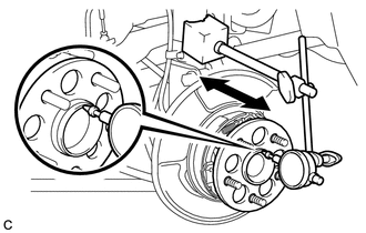
Using a dial indicator, check for looseness near the center of the rear axle hub.
Maximum looseness 0.05 mm (0.00197 in.) Note
-
Ensure that the dial indicator is set perpendicular to the measurement surface.
-
Keep the magnet of the dial indicator away from the rear axle hub and bearing assembly.
If the looseness exceeds the maximum, replace the rear axle hub and bearing assembly.
-
-
-
INSPECT REAR AXLE HUB RUNOUT
-
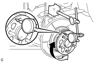
Using a dial indicator, check for runout on the surface of the rear axle hub outside the rear axle hub bolts.
Maximum runout 0.07 mm (0.00276 in.) Note
-
Ensure that the dial indicator is set perpendicular to the measurement surface.
-
Make sure to install the tip of the dial indicator towards the outside of the rear axle hub bolt.
-
Keep the magnet of the dial indicator away from the rear axle hub and bearing assembly.
If the runout exceeds the maximum, replace the rear axle hub and bearing assembly.
-
-
-
INSTALL REAR DISC
-
INSTALL PARKING BRAKE SHOE ADJUSTING HOLE PLUG
-
INSTALL REAR DISC BRAKE CALIPER ASSEMBLY
-
CONNECT CABLE TO NEGATIVE AUXILIARY BATTERY TERMINAL
-
Connect the cable to the negative (-) auxiliary battery terminal Click here.
-
Connect the reservoir level switch connector.
-
Clear the DTCs Click here.
-
-
INSTALL FRONT OUTER COWL TOP PANEL SUB-ASSEMBLY (for RHD)
-
INSTALL WINDSHIELD WIPER MOTOR AND LINK ASSEMBLY (for RHD)
Tech Tips
Use the same procedure as for LHD Click here.
-
ADJUST PARKING BRAKE
-
INSTALL REAR WHEEL
- Torque:
- 103 N*m { 1049 kgf*cm, 76 ft.*lbf }