REAR AXLE CARRIER REMOVAL
CAUTION / NOTICE / HINT
Note
When the brake pedal is first depressed after replacing the brake pads or pushing back the disc brake piston, DTC C1214 may be output. As there is no malfunction, clear the DTC.
Tech Tips
-
Use the same procedure for the RH side and LH side.
-
The procedure listed below is for the LH side.
PROCEDURE
-
PRECAUTION
Note
After turning the power switch off, waiting time may be required before disconnecting the cable from the negative (-) auxiliary battery terminal. Therefore, make sure to read the disconnecting the cable from the negative (-) auxiliary battery terminal notice before proceeding with work Click here.
-
DISABLE BRAKE CONTROL (for LHD)
-
REMOVE WINDSHIELD WIPER MOTOR AND LINK ASSEMBLY (for RHD)
Tech Tips
Use the same procedure as for LHD Click here.
-
REMOVE FRONT OUTER COWL TOP PANEL SUB-ASSEMBLY (for RHD)
-
DISABLE BRAKE CONTROL (for RHD)
-
REMOVE REAR WHEEL
-
SEPARATE REAR DISC BRAKE CALIPER ASSEMBLY
-
REMOVE PARKING BRAKE SHOE ADJUSTING HOLE PLUG
-
REMOVE REAR DISC
-
DISCONNECT SKID CONTROL SENSOR WIRE
-
REMOVE REAR AXLE HUB AND BEARING ASSEMBLY
-
REMOVE REAR HEIGHT CONTROL SENSOR SUB-ASSEMBLY (for RH Side)
-
SEPARATE REAR STRUT ROD ASSEMBLY
-
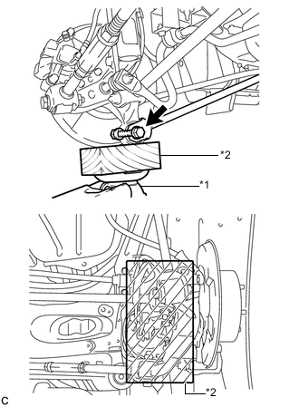
Text in Illustration *1 Jack *2 Wooden Block Use a jack and wooden block to support the rear axle carrier sub-assembly.
-
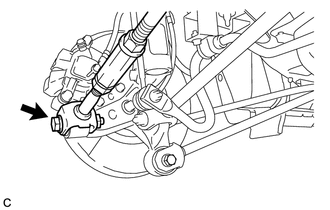
Remove the bolt and nut, and separate the rear strut rod assembly (rear side) from the rear axle carrier sub-assembly.
Note
When removing the bolt, keep the nut from rotating.
-
-
SEPARATE REAR NO. 2 SUSPENSION ARM ASSEMBLY
-
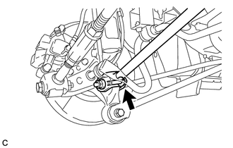
Remove the bolt and nut, and separate the rear No. 2 suspension arm assembly (outer side) from the rear axle carrier sub-assembly.
Note
When removing the bolt, keep the nut from rotating.
-
-
SEPARATE REAR NO. 1 SUSPENSION ARM ASSEMBLY
-
Remove the bolt and nut, and separate the rear No. 1 suspension arm assembly (outer side) from the rear axle carrier sub-assembly.
Note
When removing the bolt, keep the nut from rotating.
-
-
REMOVE REAR AXLE CARRIER SUB-ASSEMBLY
-
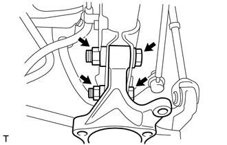
Remove the 2 bolts, 2 nuts and rear axle carrier sub-assembly from the rear shock absorber assembly.
Note
When removing the nuts, keep the bolts from rotating.
-