STEERING GEAR REMOVAL

Info Added 2017-10-06 ![]()
CAUTION / NOTICE / HINT
The necessary procedures (adjustment, calibration, initialization, or registration) that must be performed after parts are removed and installed, or replaced during steering gear assembly removal/installation are shown below.
| Replaced Part or Performed Procedure | Necessary Procedure | Effect/Inoperative Function when Necessary Procedure not Performed | Link |
|---|---|---|---|
| Front wheel alignment adjustment |
|
|
PROCEDURE
-
ALIGN FRONT WHEELS FACING STRAIGHT AHEAD
-
SECURE STEERING WHEEL ASSEMBLY
-
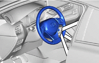
Secure the steering wheel with the seat belt in order to prevent rotation.
Tech Tips
This operation is useful to prevent damage to the spiral cable.
-
-
REMOVE COLUMN HOLE COVER SILENCER SHEET
-
SEPARATE NO. 2 STEERING INTERMEDIATE SHAFT ASSEMBLY
-
SEPARATE NO. 1 STEERING COLUMN HOLE COVER SUB-ASSEMBLY
-
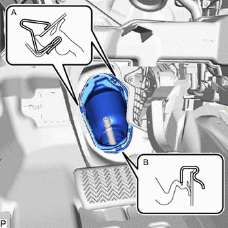
Separate the clip (A), disengage the clip (B) from the vehicle body and separate the No. 1 steering column hole cover sub-assembly.
Note
Do not damage the clips (A) or (B).
-
-
REMOVE FRONT WHEELS
-
SEPARATE TIE ROD END SUB-ASSEMBLY LH
-
Remove the cotter pin and nut.
-
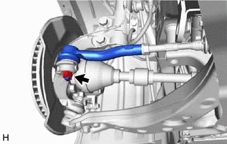
Install SST to the tie rod end sub-assembly LH.
- SST
- 09960-20010 ( 09961-02060 )
Note
Make sure that the upper ends of the tie rod end sub-assembly LH and SST are aligned.
-
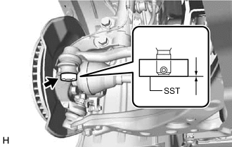
Secure SST using a string.
Note
Be sure to tighten the string firmly to secure SST to the steering knuckle LH to prevent SST from falling off.
-
Using SST, separate the tie rod end sub-assembly LH from the steering knuckle LH.
- SST
- 09960-20010 ( 09961-02010 )
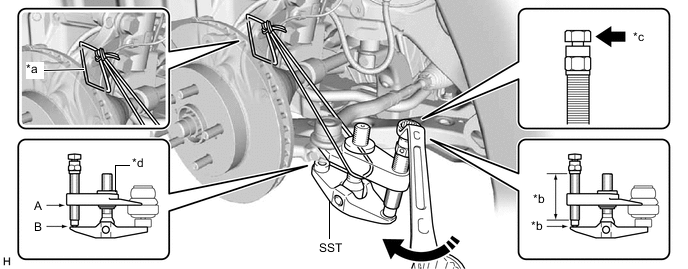
*a String *b Molybdenum Grease Application Area *c Place wrench here *d Center Nut 
Turn - - CAUTION:
Apply molybdenum grease to the bolt threads and the tip of SST.
Note
-
Be sure to tighten the string firmly to secure SST to the steering knuckle LH to prevent SST from falling off.
-
Install SST with the center nut so that (A) and (B) shown in the illustration are parallel. Otherwise, the ball joint dust cover may be damaged.
-
Be sure to place the wrench on the part shown in the illustration.
-
Do not damage the front disc brake dust cover.
-
Do not damage the ball joint dust cover.
-
Do not damage the steering knuckle LH.
-
-
SEPARATE TIE ROD END SUB-ASSEMBLY RH
Tech Tips
Perform the same procedure as for the LH side.
-
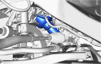
REMOVE STEERING LINK ASSEMBLY
-
for AWD:
-
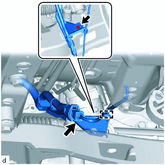
Disengage the clamp and disconnect the connector.
-
Remove the bolt and separate the wire harness clamp bracket from the front suspension crossmember sub-assembly.
-
-
for 2WD:
-
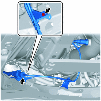
Disconnect the connector.
-
Remove the bolt and separate the wire harness clamp bracket from the front suspension crossmember sub-assembly.
-
-
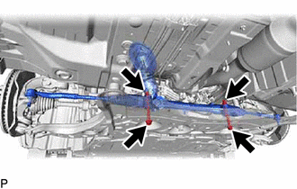
Remove the 2 bolts, 2 nuts and steering link assembly from the front suspension crossmember sub-assembly.
Note
Because the nut has its own stopper, do not turn the nut. Loosen the bolt with the nut secured.
-
Remove the No. 1 steering column hole cover sub-assembly from the steering link assembly.
-
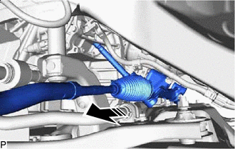
Remove in this Direction Remove the steering link assembly as shown in the illustration.
-
-
SECURE STEERING LINK ASSEMBLY
-
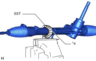
*a Protective Tape Using SST, secure the steering link assembly in a vise.
- SST
- 09612-00012
Tech Tips
Wrap SST with protective tape before use.
-
-
REMOVE TIE ROD END SUB-ASSEMBLY LH
-
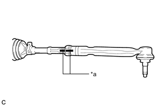
*a Matchmark Put matchmarks on the tie rod end sub-assembly LH and steering gear assembly.
-
Remove the tie rod end sub-assembly LH and lock nut.
-
-
REMOVE TIE ROD END SUB-ASSEMBLY RH
Tech Tips
Perform the same procedure as for the LH side.