FORCED RELEASE OPERATION METHOD

Info Added 2017-10-06 ![]()
PROCEDURE
-
PRECAUTION
-
REMOVE DECK BOARD ASSEMBLY (w/ Deck Board)
-
REMOVE SPARE WHEEL CUSHION (w/ Deck Board)
-
REMOVE DECK FLOOR BOX LH (w/ Deck Floor Box)
-
REMOVE DECK FLOOR BOX RH (w/ Deck Floor Box)
-
PARKING BRAKE FORCED RELEASE
CAUTION:
Work on a level surface to ensure safety.
Note
-
To release the parking brake, follow the procedure for when using SST.
-
If the parking brake cannot be released, follow the procedure for when not using SST.
-
When moving the vehicle after releasing the parking brake, install all parts except the connector shown in the illustration.
-
If the ignition switch ON or the engine is started with the connector disconnected, a DTC may be stored. Clear any DTCs after performing work.
-
When using SST:
-
Park the vehicle on a level surface and move the shift lever to P.
-
Turn the ignition switch off and chock the wheels.
-
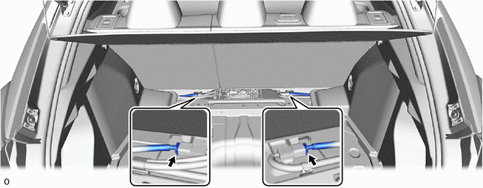
Disconnect the connector shown in the illustration.
-
Connect SST (09756-48020) to SST (09756-48070).
- SST
- 09756-48020
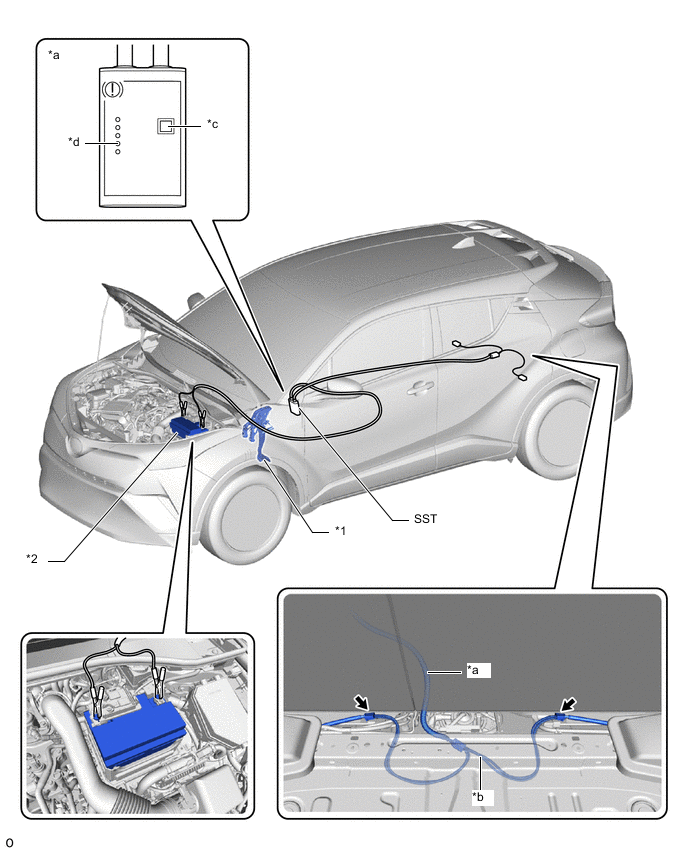
*1 Brake Pedal Support Assembly *2 Battery *a SST(09756-48020) *b SST(09756-48070) *c Release Button *d Finished Light 
Connector - - -
Connect SST (09756-48070) to the connector inside of the vehicle.
-
Connect SST (09756-48020) to the battery from the outside of the vehicle.
-
Push the release button on SST (09756-48020) with the brake pedal depressed.
CAUTION:
The vehicle may suddenly move when the parking brake is released. Make sure to perform the release operation with the brake pedal depressed.
Tech Tips
-
Confirm that the parking brake is operating by listening for operation sounds.
-
If no operation sounds are heard, push the release button on SST with the brake pedal depressed.
-
The parking brake may not release if the battery voltage is too low. In this case, perform the release operation again using a fully charged or new battery.
-
-
When the FINISHED light of SST (09756-48020) illuminates, release the brake pedal.
-
Move the vehicle forward and rearward to check that the parking brake is released.
CAUTION:
Be careful when performing this operation. The vehicle may suddenly move.
Note
-
When moving the vehicle after releasing the parking brake, check that the connector is disconnected.
-
The brake warning light (yellow) will illuminate when the vehicle is moved after releasing the parking brake.
-
-
-
When not using SST:
Note
Perform the following procedure only when the parking brake cannot be released using SST.
Tech Tips
-
Use the same procedure for the RH side and LH side.
-
The following procedure is for the LH side.
-
Park the vehicle on a level surface and check that the shift lever is in P.
-
Turn the ignition switch off and check that the wheels are chocked.
-
Check that the connector shown in the illustration has been disconnected.
-
Remove the rear wheel.
CAUTION:
When using a jack, do not work on a vehicle supported only by jacks. Make sure to use safety stands.
-
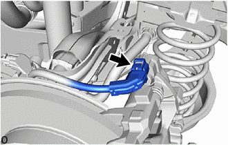
Disconnect the No. 2 parking brake wire assembly connector from the parking brake actuator assembly.
-
Remove the parking brake actuator assembly from the rear disc brake cylinder assembly.
-
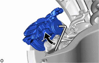
Insert a 6 mm hexagon wrench into the rear disc brake cylinder assembly.
-
Turn the 6 mm hexagon wrench 2 turns clockwise to release the parking brake lock.
Note
-
When moving the vehicle after releasing the parking brake, install all parts except the connector shown in the illustration.
-
The brake warning light (yellow) will illuminate when the vehicle is moved after releasing the parking brake.
-
-
-
-
INSTALL DECK FLOOR BOX LH (w/ Deck Floor Box)
-
INSTALL DECK FLOOR BOX RH (w/ Deck Floor Box)
-
INSTALL SPARE WHEEL CUSHION (w/ Deck Board)
-
INSTALL DECK BOARD ASSEMBLY (w/ Deck Board)