VEHICLE STABILITY CONTROL SYSTEM, Diagnostic DTC:C1380

| DTC Code | DTC Name |
|---|---|
| C1380 | Stop Light Control Relay Malfunction |
DESCRIPTION
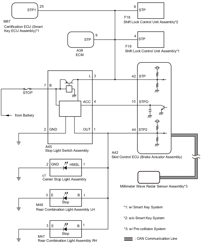
When the dynamic radar cruise control system*1, pre-collision system*1 or brake hold control system operates, the skid control ECU outputs a stop light drive output (STPO) signal to illuminate the stop lights.
*1: w/ Pre-collision System
| DTC No. | Detection Item | DTC Detection Condition | Trouble Area |
|---|---|---|---|
| C1380 | Stop Light Control Relay Malfunction | Either condition is met:
|
|
| Vehicle Condition | |||
|---|---|---|---|
| Pattern 1 | Pattern 2 | ||
| Diagnosis Condition | - | - | - |
| Malfunction Status | When the voltage at the +BS terminal is between 10 V or more and the stop light control relay drive output (STPO) is on, a signal is not input to the STP2 terminal. | ○ | - |
| When the voltage at the +BS terminal is between 10 V or more and the stop light control relay drive output (STPO) is off, the signal at the STP terminal is different from the input signal at the STP2 terminal. | - | ○ | |
| Detection Time | 5 seconds or more | 5 seconds or more | |
| Number of Trips | 1 trip | 1 trip | |
Tech Tips
DTC will be output when conditions for either of the patterns in the table above are met.
WIRING DIAGRAM
CAUTION / NOTICE / HINT
Note
-
When replacing the skid control ECU (brake actuator assembly), perform system variant learning.
-
Inspect the fuses for circuits related to this system before performing the following procedure.
-
Before replacing the certification ECU (smart key ECU assembly), refer to Service Bulletin*1.
-
*1: w/ Entry and Start System
PROCEDURE
-
CHECK HARNESS AND CONNECTOR (STP, STPO AND STP2 TERMINAL)
-
Turn the ignition switch off.
-
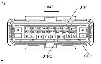
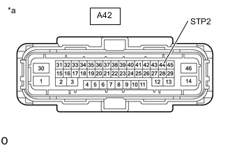
*a Front view of wire harness connector
(to Skid Control ECU (Brake Actuator Assembly))
Disconnect the skid control ECU (brake actuator assembly) connector.
-
Measure the voltage according to the value(s) in the table below.
Standard Voltage Tester Connection Condition Specified Condition A42-42 (STP) - Body ground Brake pedal depressed 11 to 14 V Brake pedal released Below 1.5 V A42-10 (STPO) - Body ground Always 11 to 14 V A42-44 (STP2) - Body ground Brake pedal depressed 11 to 14 V Brake pedal released Below 1.5 V Result Result Proceed to All terminal voltage is normal A Only STP terminal voltage abnormal B Only STPO terminal voltage abnormal C Only STP2 terminal voltage abnormal D STPO terminal and STP2 terminal voltage abnormal E
B 
CHECK HARNESS AND CONNECTOR (BRAKE ACTUATOR ASSEMBLY - ECM) Click here
C
CHECK HARNESS AND CONNECTOR (BRAKE ACTUATOR ASSEMBLY - STOP LIGHT SWITCH ASSEMBLY) Click here
D
CHECK HARNESS AND CONNECTOR (BRAKE ACTUATOR ASSEMBLY - REAR COMBINATION LIGHT ASSEMBLY LH) Click here
E
CHECK STOP LIGHT SWITCH ASSEMBLY POWER SOURCE CIRCUIT Click here
A 
-
-
PERFORM ACTIVE TEST USING GTS (STOP LIGHT RELAY)
-
Enter the following menus: Chassis / ABS/VSC/TRC/EPB / Active Test.
-
Perform "Active Test" according to the display on the GTS.
Chassis > ABS/VSC/TRC/EPB > Active TestTester Display Measurement Item Control Range Diagnostic Note Stop Light Relay Stop light control relay (Stop light switch assembly) ON or OFF Stop lights come on
Chassis > ABS/VSC/TRC/EPB > Active TestTester Display Stop Light Relay OK Stop light turns ON/OFF in response to the GTS operation Result Proceed to OK NG
NG
INSPECT BRAKE ACTUATOR ASSEMBLY Click here
OK
-
-
CHECK FOR DTC
-
Clear the DTCs.
Chassis > ABS/VSC/TRC/EPB > Clear DTCs -
Enter the following menus: Chassis / ABS/VSC/TRC/EPB / Active Test.
-
Perform "Active Test" according to the display on the GTS.
Chassis > ABS/VSC/TRC/EPB > Active TestTester Display Measurement Item Control Range Diagnostic Note Stop Light Relay Stop light control relay (Stop light switch assembly) ON or OFF Stop lights come on
Chassis > ABS/VSC/TRC/EPB > Active TestTester Display Stop Light Relay -
Check for DTCs.
Chassis > ABS/VSC/TRC/EPB > Clear DTCsResult Result Proceed to DTC C1380 is output. (for LHD) A DTC C1380 is output. (for RHD) B DTC C1380 is not output. C
A 
REPLACE BRAKE ACTUATOR ASSEMBLY Click here
B
REPLACE BRAKE ACTUATOR ASSEMBLY Click here
C
USE SIMULATION METHOD TO CHECK Click here
-
-
INSPECT BRAKE ACTUATOR ASSEMBLY
-
Enter the following menus: Chassis / ABS/VSC/TRC/EPB / Active Test.
-
Perform "Active Test" according to the display on the GTS.
Chassis > ABS/VSC/TRC/EPB > Active TestTester Display Measurement Item Control Range Diagnostic Note Stop Light Relay Stop light control relay (Stop light switch assembly) ON or OFF Stop lights come on
Chassis > ABS/VSC/TRC/EPB > Active TestTester Display Stop Light Relay -
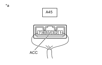
*a Component with harness connected
(Stop Light Switch Assembly)
Measure the voltage according to the value(s) in the table below.
Standard Voltage Tester Connection Condition Specified Condition A45-4 (ACC) - Body ground Active Test is ON Below 1.5 V Result Result Proceed to OK A NG (for LHD) B NG (for RHD) C
A
REPLACE STOP LIGHT SWITCH ASSEMBLY Click here
B
REPLACE BRAKE ACTUATOR ASSEMBLY Click here
C
REPLACE BRAKE ACTUATOR ASSEMBLY Click here
-
-
CHECK HARNESS AND CONNECTOR (BRAKE ACTUATOR ASSEMBLY - ECM)
-
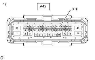
*a Front view of wire harness connector
(to Skid Control ECU (Brake Actuator Assembly))
Make sure that there is no looseness at the locking part and the connecting part of the connector.
OK The connector is securely connected. -
Disconnect the A38 ECM connector.
-
Check both the connector case and the terminals for deformation and corrosion.
OK No deformation or corrosion. -
Measure the voltage according to the value(s) in the table below.
Standard Voltage Tester Connection Condition Specified Condition A42-42 (STP) - Body ground Stop light switch assembly on (Brake pedal depressed) 11 to 14 V* A42-42 (STP) - Body ground Stop light switch assembly off (Brake pedal released) Below 1.5 V Tech Tips
*: The standard voltage value varies depending on the +BS terminal voltage value. The standard voltage is 85% of the +BS terminal voltage.
Result Result Proceed to OK (for 8NR-FTS) A OK (for 3ZR-FAE) B NG (w/ Entry and Start System) C NG (w/o Entry and Start System) D
A
REPLACE ECM Click here
B
REPLACE ECM Click here
D
CHECK HARNESS AND CONNECTOR (BRAKE ACTUATOR ASSEMBLY - SHIFT LOCK CONTROL UNIT ASSEMBLY) Click here
C
-
-
CHECK HARNESS AND CONNECTOR (BRAKE ACTUATOR ASSEMBLY - SMART KEY ECU ASSEMBLY)
-
*a Front view of wire harness connector
(to Skid Control ECU (Brake Actuator Assembly))
Make sure that there is no looseness at the locking part and the connecting part of the connector.
OK The connector is securely connected. -
Disconnect the M67 certification ECU (smart key ECU assembly) connector.
-
Check both the connector case and the terminals for deformation and corrosion.
OK No deformation or corrosion. -
Measure the voltage according to the value(s) in the table below.
Standard Voltage Tester Connection Condition Specified Condition A42-42 (STP) - Body ground Stop light switch assembly on (Brake pedal depressed) 11 to 14 V* A42-42 (STP) - Body ground Stop light switch assembly off (Brake pedal released) Below 1.5 V Tech Tips
*: The standard voltage value varies depending on the +BS terminal voltage value. The standard voltage is 85% of the +BS terminal voltage.
Result Proceed to OK NG
OK
REPLACE SMART KEY ECU ASSEMBLY
NG
-
-
CHECK HARNESS AND CONNECTOR (BRAKE ACTUATOR ASSEMBLY - SHIFT LOCK CONTROL UNIT ASSEMBLY)
-
*a Front view of wire harness connector
(to Skid Control ECU (Brake Actuator Assembly))
Make sure that there is no looseness at the locking part and the connecting part of the connector.
OK The connector is securely connected. -
Disconnect the F19 shift lock control ECU (shift lock control unit assembly) connector.
-
Check both the connector case and the terminals for deformation and corrosion.
OK No deformation or corrosion. -
Measure the voltage according to the value(s) in the table below.
Standard Voltage Tester Connection Condition Specified Condition A42-42 (STP) - Body ground Stop light switch assembly on (Brake pedal depressed) 11 to 14 V* A42-42 (STP) - Body ground Stop light switch assembly off (Brake pedal released) Below 1.5 V Tech Tips
*: The standard voltage value varies depending on the +BS terminal voltage value. The standard voltage is 85% of the +BS terminal voltage.
Result Result Proceed to OK (for K114) A OK (for K313) B OK (for K313F) C NG D
A
REPLACE SHIFT LOCK CONTROL UNIT ASSEMBLY Click here
B
REPLACE SHIFT LOCK CONTROL UNIT ASSEMBLY Click here
C
REPLACE SHIFT LOCK CONTROL UNIT ASSEMBLY Click here
D
-
-
CHECK HARNESS AND CONNECTOR (BRAKE ACTUATOR ASSEMBLY - STOP LIGHT SWITCH ASSEMBLY)
-
*a Front view of wire harness connector
(to Skid Control ECU (Brake Actuator Assembly))
Make sure that there is no looseness at the locking part and the connecting part of the connector.
OK The connector is securely connected. -
Disconnect the A45 stop light switch assembly connector.
-
Check both the connector case and the terminals for deformation and corrosion.
OK No deformation or corrosion. -
Measure the voltage according to the value(s) in the table below.
Standard Voltage Tester Connection Condition Specified Condition A42-42 (STP) - Body ground Always Below 1.5 V Result Proceed to OK NG
NG
REPAIR OR REPLACE HARNESS OR CONNECTOR
OK
-
-
CHECK HARNESS AND CONNECTOR (BRAKE ACTUATOR ASSEMBLY - STOP LIGHT SWITCH ASSEMBLY)
-
Turn the ignition switch off.
-
Disconnect the A42 skid control ECU (brake actuator assembly) connector.
-
Disconnect the A45 stop light switch assembly connector.
-
Measure the resistance according to the value(s) in the table below.
Standard Resistance Tester Connection Condition Specified Condition A42-42 (STP) - A45-3 (L) Always Below 1 Ω A42-42 (STP) or A45-3 (L) - Body ground Always 10 kΩ or higher Result Proceed to OK NG
OK
REPLACE STOP LIGHT SWITCH ASSEMBLY Click here
NG
REPAIR OR REPLACE HARNESS OR CONNECTOR
-
-
CHECK HARNESS AND CONNECTOR (BRAKE ACTUATOR ASSEMBLY - SHIFT LOCK CONTROL UNIT ASSEMBLY)
-
*a Front view of wire harness connector
(to Skid Control ECU (Brake Actuator Assembly))
Make sure that there is no looseness at the locking part and the connecting part of the connector.
OK The connector is securely connected. -
Disconnect the F18 shift lock control ECU (shift lock control unit assembly) connector.
-
Check both the connector case and the terminals for deformation and corrosion.
OK No deformation or corrosion. -
Measure the voltage according to the value(s) in the table below.
Standard Voltage Tester Connection Condition Specified Condition A42-42 (STP) - Body ground Stop light switch assembly on (Brake pedal depressed) 11 to 14 V* A42-42 (STP) - Body ground Stop light switch assembly off (Brake pedal released) Below 1.5 V Tech Tips
*: The standard voltage value varies depending on the +BS terminal voltage value. The standard voltage is 85% of the +BS terminal voltage.
Result Result Proceed to OK (for K114) A OK (for K313) B OK (for K313F) C NG D
A
REPLACE SHIFT LOCK CONTROL UNIT ASSEMBLY Click here
B
REPLACE SHIFT LOCK CONTROL UNIT ASSEMBLY Click here
C
REPLACE SHIFT LOCK CONTROL UNIT ASSEMBLY Click here
D
-
-
CHECK HARNESS AND CONNECTOR (BRAKE ACTUATOR ASSEMBLY - STOP LIGHT SWITCH ASSEMBLY)
-
*1 Front view of wire harness connector
(to Skid Control ECU (Brake Actuator Assembly))
Make sure that there is no looseness at the locking part and the connecting part of the connector.
OK The connector is securely connected. -
Disconnect the A45 stop light switch assembly connector.
-
Check both the connector case and the terminals for deformation and corrosion.
OK No deformation or corrosion. -
Measure the voltage according to the value(s) in the table below.
Standard Voltage Tester Connection Condition Specified Condition A42-42 (STP) - Body ground Always Below 1.5 V Result Proceed to OK NG
NG
REPAIR OR REPLACE HARNESS OR CONNECTOR
OK
-
-
CHECK HARNESS AND CONNECTOR (BRAKE ACTUATOR ASSEMBLY - STOP LIGHT SWITCH ASSEMBLY)
-
Measure the resistance according to the value(s) in the table below.
Standard Resistance Tester Connection Condition Specified Condition A42-42 (STP) - A45-3 (L) Always Below 1 Ω A42-42 (STP) or A45-3 (L) - Body ground Always 10 kΩ or higher Result Proceed to OK NG
OK
REPLACE STOP LIGHT SWITCH ASSEMBLY Click here
NG
REPAIR OR REPLACE HARNESS OR CONNECTOR
-
-
CHECK HARNESS AND CONNECTOR (BRAKE ACTUATOR ASSEMBLY - STOP LIGHT SWITCH ASSEMBLY)
-
Turn the ignition switch off.
-
Disconnect the A42 skid control ECU (brake actuator assembly) connector.
-
Disconnect the A45 stop light switch assembly connector.
-
Measure the resistance according to the value(s) in the table below.
Standard Resistance Tester Connection Condition Specified Condition A42-10 (STPO) - A45-4 (ACC) Always Below 1 Ω Result Proceed to OK NG
OK
REPLACE STOP LIGHT SWITCH ASSEMBLY Click here
NG
REPAIR OR REPLACE HARNESS OR CONNECTOR
-
-
CHECK HARNESS AND CONNECTOR (BRAKE ACTUATOR ASSEMBLY - REAR COMBINATION LIGHT ASSEMBLY LH)
-
*1 Front view of wire harness connector
(to Skid Control ECU (Brake Actuator Assembly))
Turn the ignition switch off.
-
Disconnect the A42 skid control ECU (brake actuator assembly) connector.
-
Disconnect the M48 rear combination light assembly LH connector.
-
Measure the voltage according to the value(s) in the table below.
Standard Voltage Tester Connection Condition Specified Condition A42-44 (STP2) - Body ground Brake pedal depressed 11 to 14 V A42-44 (STP2) - Body ground Brake pedal released Below 1.5 V Result Reult Proceed to OK (for LED Type) A OK (for Bulb Type) B NG C
A
REPLACE REAR COMBINATION LIGHT ASSEMBLY LH Click here
B
REPLACE REAR COMBINATION LIGHT ASSEMBLY LH Click here
C
-
-
CHECK HARNESS AND CONNECTOR (BRAKE ACTUATOR ASSEMBLY - REAR COMBINATION LIGHT ASSEMBLY RH)
-
*1 Front view of wire harness connector
(to Skid Control ECU (Brake Actuator Assembly))
Turn the ignition switch off.
-
Disconnect the A42 skid control ECU (brake actuator assembly) connector.
-
Disconnect the M48 rear combination light assembly LH connector.
-
Disconnect the M47 rear combination light assembly RH connector.
-
Measure the voltage according to the value(s) in the table below.
Standard Voltage Tester Connection Condition Specified Condition A42-44 (STP2) - Body ground Brake pedal depressed 11 to 14 V A42-44 (STP2) - Body ground Brake pedal released Below 1.5 V Result Result Proceed to OK (for LED Type) A OK (for Bulb Type) B NG C
A
REPLACE REAR COMBINATION LIGHT ASSEMBLY RH Click here
B
REPLACE REAR COMBINATION LIGHT ASSEMBLY RH Click here
C
-
-
CHECK HARNESS AND CONNECTOR (BRAKE ACTUATOR ASSEMBLY - CENTER STOP LIGHT ASSEMBLY)
-
*1 Front view of wire harness connector
(to Skid Control ECU (Brake Actuator Assembly))
Turn the ignition switch off.
-
Disconnect the A42 skid control ECU (brake actuator assembly) connector.
-
Disconnect the M48 rear combination light assembly LH connector.
-
Disconnect the M47 rear combination light assembly RH connector.
-
Disconnect the c1 center stop light assembly connector.
-
Measure the voltage according to the value(s) in the table below.
Standard Voltage Tester Connection Condition Specified Condition A42-44 (STP2) - Body ground Brake pedal depressed 11 to 14 V A42-44 (STP2) - Body ground Brake pedal released Below 1.5 V Result Proceed to OK NG
OK
REPLACE CENTER STOP LIGHT ASSEMBLY Click here
NG
-
-
CHECK HARNESS AND CONNECTOR (BRAKE ACTUATOR ASSEMBLY - STOP LIGHT SWITCH ASSEMBLY)
-
Turn the ignition switch off.
-
Disconnect the A42 skid control ECU (brake actuator assembly) connector.
-
Disconnect the M48 rear combination light assembly LH connector.
-
Disconnect the M47 rear combination light assembly RH connector.
-
Disconnect the c1 center stop light assembly connector.
-
Disconnect the A45 stop light switch assembly connector.
-
Measure the resistance according to the value(s) in the table below.
Standard Resistance Tester Connection Condition Specified Condition A45-1 (OUT) - A42-44 (STP2) Always Below 1 Ω A45-1 (OUT) or A42-44 (STP2) - Body ground Always 10 kΩ or higher Result Proceed to OK NG
OK
REPLACE STOP LIGHT SWITCH ASSEMBLY Click here
NG
REPAIR OR REPLACE HARNESS OR CONNECTOR
-
-
CHECK STOP LIGHT SWITCH ASSEMBLY POWER SOURCE CIRCUIT
-
Turn the ignition switch off.
-
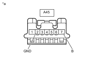
*a Front view of wire harness connector
(to Stop Light Switch Assembly)
Disconnect the stop light switch assembly connector.
-
Measure the resistance according to the value(s) in the table below.
Standard Resistance Tester Connection Condition Specified Condition A45-2 (GND) - Body ground Always Below 1 Ω -
Measure the voltage according to the value(s) in the table below.
Standard Voltage Tester Connection Condition Specified Condition A45-7 (B) - Body ground Always 11 to 14 V Result Proceed to OK NG
NG
REPAIR OR REPLACE HARNESS OR CONNECTOR
OK
-
-
CHECK HARNESS AND CONNECTOR (BRAKE ACTUATOR ASSEMBLY - STOP LIGHT SWITCH ASSEMBLY)
-
Turn the ignition switch off.
-
Disconnect the A42 skid control ECU (brake actuator assembly) connector.
-
Disconnect the A45 stop light switch assembly connector.
-
Measure the resistance according to the value(s) in the table below.
Standard Resistance Tester Connection Condition Specified Condition A42-10 (STPO) - A45-4 (ACC) Always Below 1 Ω Result Proceed to OK NG
OK
REPLACE STOP LIGHT SWITCH ASSEMBLY Click here
NG
REPAIR OR REPLACE HARNESS OR CONNECTOR
-