TIRE PRESSURE WARNING SYSTEM TC and CG Terminal Circuit
DESCRIPTION
Tire pressure warning system DTCs can be checked by connecting terminals 13 (TC) and 4 (CG) of the DLC3. The DTCs are indicated by blinking the tire pressure warning light.
WIRING DIAGRAM
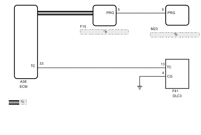
| *a | Main Body ECU (Multiplex Network Body ECU) |
| *b | Tire Pressure Warning ECU and Receiver |
| *c | CAN Communication Line |
CAUTION / NOTICE / HINT
Note
-
When replacing the tire pressure warning ECU and receiver, read the transmitter IDs stored in the old ECU using the GTS and write them down before removal.
-
It is necessary to perform initialization after registration Click here of the transmitter IDs into the tire pressure warning ECU and receiver if the ECU has been replaced
PROCEDURE
-
CHECK CAN COMMUNICATION SYSTEM
-
Check for DTCs.
Result Result Proceed to DTCs are not output. A DTCs are output. B
B 
GO TO CAN COMMUNICATION SYSTEM Click here
A 
-
-
CHECK DTC (C2179/79)
-
Check if DTC C2179/79 is output.
Chassis > Tire Pressure Monitor > Trouble CodesResult Result Proceed to DTC C2179/79 is not output. A DTC C2179/79 is output. B
B
GO TO DTC C2179/79 Click here
A
-
-
CHECK HARNESS AND CONNECTOR (TC of DLC3 - ECM)
-
Disconnect the A38 ECM connector.
-
Measure the resistance according to the value(s) in the table below.
Standard Resistance Tester Connection Condition Specified Condition F41-13 (TC) - A38-33 (TC) Always Below 1 Ω F41-13 (TC) or A38-33 (TC) - Body ground Always 10 kΩ or higher Result Proceed to OK NG
NG
REPAIR OR REPLACE HARNESS OR CONNECTOR
OK
-
-
CHECK HARNESS AND CONNECTOR (CG of DLC3 - BODY GROUND)
-
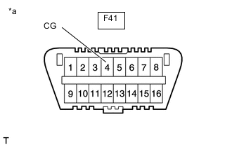
*a Front view of DLC3 Measure the resistance according to the value(s) in the table below.
Standard Resistance Tester Connection Condition Specified Condition F41-4 (CG) - Body ground Always Below 1 Ω Result Proceed to OK NG
NG
REPAIR OR REPLACE HARNESS OR CONNECTOR
OK
-
-
INSPECT DLC3 TERMINAL VOLTAGE (TC VOLTAGE)
-
Reconnect the A38 ECM connector.
-
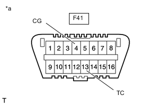
*a Front view of DLC3 Measure the voltage according to the value(s) in the table below.
Standard Voltage Tester Connection Condition Specified Condition F41-13 (TC) - F41-4 (CG) Ignition switch to ON 11 to 14 V Result Proceed to OK NG
OK
PROCEED TO NEXT SUSPECTED AREA SHOWN IN PROBLEM SYMPTOMS TABLE Click here
NG
REPLACE ECM Click here
-