CONTINUOUSLY VARIABLE TRANSAXLE SYSTEM, Diagnostic DTC:P056014
| DTC Code | DTC Name |
|---|---|
| P056014 | System Voltage Circuit Short to Ground or Open |
DESCRIPTION
The battery supplies electricity to the ECM even when the ignition switch is off. This power allows the ECM to store data such as DTC history, freeze frame data and fuel trim values. If the battery voltage falls below a minimum level, the memory is cleared and the ECM determines that there is a malfunction in the power supply circuit. The next time the engine is started, the ECM will illuminate the MIL and store this DTC.
| DTC No. | Detection Item | DTC Detection Condition | Trouble Area | MIL | Memory | Note |
|---|---|---|---|---|---|---|
| P056014 | System Voltage Circuit Short to Ground or Open | An open in the ECM backup power source circuit for 3 seconds (1 trip detection logic). |
|
Comes on | DTC stored | SAE Code: P0562 |
Tech Tips
If DTC P056014 is stored, the ECM will not store other DTCs or the data stored in the ECM will be partially cleared.
CAUTION / NOTICE / HINT
Note
-
Perform initialization when parts related to the continuously variable transaxle are replaced.
-
Check that no DTCs are stored after performing initialization.
-
After turning ignition switch off, waiting time may be required before disconnecting the cable from the negative (-) battery terminal. Therefore, make sure to read the disconnecting the cable from the negative (-) battery terminal notices before proceeding with work.
-
Inspect the fuses for circuits related to this system before performing the following procedure.
Tech Tips
-
After performing repair, clear the DTCs and perform the following procedure to check that DTCs are not output.
-
Turn the ignition switch to ON and wait for 3 seconds or more.
-
Check for DTCs again.
PROCEDURE
-
INSPECT BATTERY
-
Inspect the battery.
OK Battery voltage is between 11 and 14 V. Result Proceed to OK NG
NG 
CHARGE OR REPLACE BATTERY
OK 
-
-
CHECK BATTERY TERMINAL
-
Check that the battery terminals are not loose or corroded.
OK Battery terminals are not loose or corroded. Result Proceed to OK NG
NG
REPAIR OR REPLACE BATTERY TERMINAL
OK
-
-
CHECK HARNESS AND CONNECTOR (POWER SOURCE OF ECM)
-
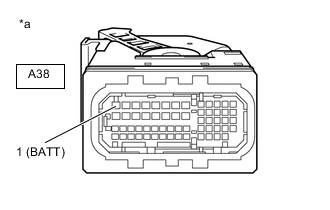
*a Front view of wire harness connector
(to ECM)
Disconnect the ECM connector.
-
Measure the voltage according to the value(s) in the table below.
Standard Voltage Tester Connection Condition Specified Condition A38-1 (BATT) - Body ground Always 11 to 14 V Result Proceed to OK NG
NG
REPAIR OR REPLACE HARNESS OR CONNECTOR (BATTERY - ECM)
OK
-
-
CHECK WHETHER DTC OUTPUT RECURS (DTC P056014)
-
Connect the GTS to the DLC3.
-
Turn the ignition switch to ON.
-
Turn the GTS on.
-
Enter the following menus: Powertrain / Transmission / Trouble Codes.
Powertrain > Transmission > Clear DTCs -
Clear the DTCs.
-
Turn the ignition switch off and wait for at least 30 seconds.
-
Turn the ignition switch to ON.
-
Turn the GTS on.
-
Wait for 3 seconds or more.
-
Enter the following menus: Powertrain / Transmission / Trouble Codes.
Powertrain > Transmission > Trouble Codes -
Read the DTCs.
Result Result Proceed to DTC P056014 is output A DTCs are not output B
B
CHECK FOR INTERMITTENT PROBLEMS Click here
A
-
-
REPLACE ECM
-
Replace the ECM.
Result Proceed to NEXT
NEXT
PERFORM INITIALIZATION Click here
-