CONTINUOUSLY VARIABLE TRANSAXLE SYSTEM, Diagnostic DTC:P074011, P074015
| DTC Code | DTC Name |
|---|---|
| P074011 | Torque Converter Clutch Circuit Short to Ground |
| P074015 | Torque Converter Clutch Circuit Short to Battery or Open |
DESCRIPTION
Based on the signal received by the shift solenoid valve SL, the ECM uses the shift solenoid valve SLU to control the lock-up clutch pressure.
If there is an open or short in the shift solenoid valve SL circuit, the ECM stops sending current to the malfunctioning shift solenoid valve.
| DTC No. | Detection Item | DTC Detection Condition | Trouble Area | MIL | Memory | Note |
|---|---|---|---|---|---|---|
| P074011 | Torque Converter Clutch Circuit Short to Ground | While the lock-up is operating, a short is detected in the shift solenoid valve SL circuit 1 time or more consecutively (1 trip detection logic). |
|
Comes on | DTC stored | SAE Code: P2769 |
| P074015 | Torque Converter Clutch Circuit Short to Battery or Open | While the lock-up is operating, an open is detected in the shift solenoid valve SL circuit 1 time or more consecutively (1 trip detection logic). |
|
Comes on | DTC stored | SAE Code: P2770 |
MONITOR DESCRIPTION
These DTCs indicate an open or short in the shift solenoid valve SL circuit. If there is an open or short in the shift solenoid valve SL circuit, the ECM detects the malfunction, illuminates the MIL and stores a DTC.
WIRING DIAGRAM
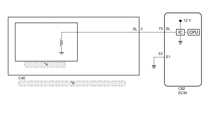
| *a | Shift Solenoid Valve SL |
| *b | Continuously Variable Transaxle Assembly (Transmission Wire) |
CAUTION / NOTICE / HINT
Note
-
Perform initialization after replacing any parts related to the continuously variable transaxle system.
-
Check that no DTCs are stored after performing initialization.
Tech Tips
After performing repair, clear the DTCs and perform the following procedure to check that DTCs are not output.
-
Drive the vehicle and confirm the lock-up on and off conditions according to Road Test.
-
Check for DTCs again.
PROCEDURE
-
INSPECT TRANSMISSION WIRE (SHIFT SOLENOID VALVE SL)
-
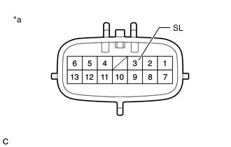
*a Component without harness connected
(Transmission Wire)
Disconnect the C40 transmission wire connector.
-
Measure the resistance according to the value(s) in the table below.
Standard Resistance Tester Connection Condition Specified Condition 3 (SL) - Body ground 20°C (68°F) 11 to 15 Ω -
Connect the C40 transmission wire connector.
Result Proceed to OK NG
NG 
REPLACE CONTINUOUSLY VARIABLE TRANSAXLE ASSEMBLY Click here
OK 
-
-
CHECK HARNESS AND CONNECTOR (TRANSMISSION WIRE - ECM)
-
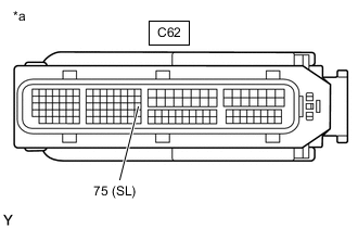
*a Front view of wire harness connector
(to ECM)
Disconnect the ECM connector.
-
Measure the resistance according to the value(s) in the table below.
Standard Resistance Tester Connection Condition Specified Condition C62-75 (SL) - Body ground 20°C (68°F) 11 to 15 Ω -
Connect the ECM connector.
Result Proceed to OK NG
NG 
REPAIR OR REPLACE HARNESS OR CONNECTOR (TRANSMISSION WIRE - ECM)
OK
-
-
REPLACE ECM
-
Replace the ECM.
Result Proceed to NEXT
NEXT
PERFORM INITIALIZATION Click here
-
-
REPLACE CONTINUOUSLY VARIABLE TRANSAXLE ASSEMBLY
-
Replace the continuously variable transaxle assembly.
-
When Not Using the Engine Support Bridge
-
When Using the Engine Support Bridge
Result Proceed to NEXT -
NEXT
PERFORM INITIALIZATION Click here
-