CONTINUOUSLY VARIABLE TRANSAXLE SYSTEM, Diagnostic DTC:P282413
| DTC Code | DTC Name |
|---|---|
| P282413 | Pressure Control Solenoid "J" Circuit Open |
DESCRIPTION
According to current from the ECM, the shift solenoid valve SLP controls primary pulley pressure in accordance with the requested gear ratio to perform gear ratio changes.
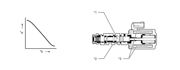
| *1 | Spool Valve | *2 | Sleeve |
| *3 | Solenoid Coil | - | - |
| *a | Hydraulic Pressure | *b | Current Flow to Solenoid |
| DTC No. | Detection Item | DTC Detection Condition | Trouble Area | MIL | Memory | Note |
|---|---|---|---|---|---|---|
| P282413 | Pressure Control Solenoid "J" Circuit Open | While the vehicle is driven, an open or a short is detected in the shift solenoid valve SLP circuit for 1 second or more (1 trip detection logic). |
|
Comes on | DTC stored | SAE Code: P2822 |
MONITOR DESCRIPTION
This DTC indicates an open or short in the shift solenoid valve SLP circuit. If there is an open or short in the shift solenoid valve SLP circuit, the ECM detects the malfunction, illuminates the MIL* and stores this DTC.
*: Euro-OBD
WIRING DIAGRAM
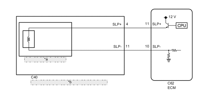
| *a | Shift Solenoid Valve SLP |
| *b | Continuously Variable Transaxle Assembly (Transmission Wire) |
CAUTION / NOTICE / HINT
Note
-
Perform initialization after replacing any parts related to the continuously variable transaxle system.
-
Check that no DTCs are stored after performing initialization.
Tech Tips
After performing repair, clear the DTCs and perform the following procedure to check that DTCs are not output.
-
Perform the D position test in Road Test.
-
Check for DTCs again.
PROCEDURE
-
INSPECT TRANSMISSION WIRE (SHIFT SOLENOID VALVE SLP)
-
*a Component without harness connected
(Transmission Wire)
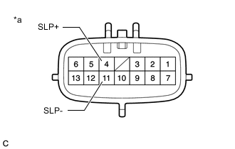
Disconnect the C40 transmission wire connector.
-
Measure the resistance according to the value(s) in the table below.
Standard Resistance Tester Connection Condition Specified Condition 4 (SLP+) - 11 (SLP-) 20°C (68°F) 5.0 to 5.6 Ω 4 (SLP+) - Body ground and other terminals Always 10 kΩ or higher 11 (SLP-) - Body ground and other terminals Always 10 kΩ or higher -
Connect the C44 transmission wire connector.
Result Proceed to OK NG
NG 
REPLACE CONTINUOUSLY VARIABLE TRANSAXLE ASSEMBLY Click here
OK 
-
-
CHECK HARNESS AND CONNECTOR (TRANSMISSION WIRE - ECM)
-
*a Front view of wire harness connector
(to ECM)
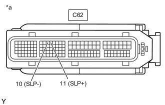
Disconnect the ECM connector.
-
Measure the resistance according to the value(s) in the table below.
Standard Resistance Tester Connection Condition Specified Condition C62-11 (SLP+) - C62-10 (SLP-) 20°C (68°F) 5.0 to 5.6 Ω C62-11 (SLP+) - Body ground and other terminals Always 10 kΩ or higher C62-10 (SLP-) - Body ground and other terminals Always 10 kΩ or higher -
Connect the ECM connector.
Result Proceed to OK NG
NG 
REPAIR OR REPLACE HARNESS OR CONNECTOR (TRANSMISSION WIRE - ECM)
OK
-
-
REPLACE ECM
-
Replace the ECM.
Result Proceed to NEXT
NEXT
PERFORM INITIALIZATION Click here
-
-
REPLACE CONTINUOUSLY VARIABLE TRANSAXLE ASSEMBLY
-
Replace the continuously variable transaxle assembly.
-
When Not Using the Engine Support Bridge
-
When Using the Engine Support Bridge
Result Proceed to NEXT -
NEXT
PERFORM INITIALIZATION Click here
-