BACK-UP LIGHT SWITCH REMOVAL
CAUTION / NOTICE / HINT
The necessary procedures (adjustment, calibration, initialization, or registration) that must be performed after parts are removed, installed, or replaced during the back-up light switch assembly removal/installation are shown below.
| Replacement Part or Procedure | Necessary Procedure | Effect/Inoperative when not Performed | Link |
|---|---|---|---|
| Disconnect cable from negative battery terminal | Memorize steering angle neutral point |
|
|
| Initialize back door lock | Power door lock control system |
-
*1: When performing learning using the GTS.
PROCEDURE
-
PRECAUTION
Note
After turning the ignition switch off, waiting time may be required before disconnecting the cable from the negative (-) battery terminal. Therefore, make sure to read the disconnecting the cable from the negative (-) battery terminal notices before proceeding with work.
-
DISCONNECT CABLE FROM NEGATIVE BATTERY TERMINAL
Note
When disconnecting the cable, some systems need to be initialized after the cable is reconnected.
-
REMOVE BATTERY
-
REMOVE RADIATOR COVER
-
REMOVE NO. 1 AIR CLEANER INLET
-
REMOVE AIR CLEANER CAP SUB-ASSEMBLY
-
REMOVE AIR CLEANER CASE SUB-ASSEMBLY
-
REMOVE ECM
-
REMOVE BATTERY CLAMP SUB-ASSEMBLY
-
REMOVE BACK-UP LIGHT SWITCH ASSEMBLY
-
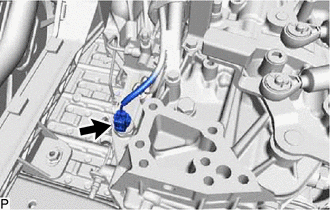
Disconnect the back-up light switch assembly connector.
-
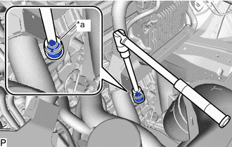
*a 27 mm Deep Socket Wrench Using a 27 mm deep socket wrench, remove the back-up light switch assembly and gasket from the manual transaxle assembly.
-