MANUAL TRANSAXLE SYSTEM, Diagnostic DTC:P080512, P080514
| DTC Code | DTC Name |
|---|---|
| P080512 | Clutch Position Sensor "A"Circuit Short to Battery |
| P080514 | Clutch Position Sensor "A"Circuit Short to Ground or Open |
DESCRIPTION
The clutch pedal stroke sensor assembly is mounted on the clutch pedal and detect the clutch pedal position and send signals to the ECM.
| DTC No. | Detection Item | DTC Detection Condition | Trouble Area | MIL | Memory | Note |
|---|---|---|---|---|---|---|
| P080512 | Clutch Position Sensor "A"Circuit Short to Battery | Clutch stroke sensor signal voltage is 4.8 V or more for 0.5 seconds or more (1 trip detection logic) |
|
Does not come on | DTC stored | SAE Code: P0808 |
| P080514 | Clutch Position Sensor "A"Circuit Short to Ground or Open | Clutch stroke sensor signal voltage is 0.2 V or less for 0.5 seconds or more (1 trip detection logic) |
|
Does not come on | DTC stored | SAE Code: P0807 |
WIRING DIAGRAM
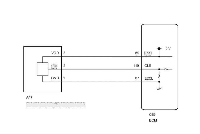
| *a | VCCL |
| *b | OUT |
| *c | Clutch Pedal Stroke Sensor Assembly |
CAUTION / NOTICE / HINT
Tech Tips
After the repair, clear the DTCs and perform the following procedure to check that DTCs are not output.
-
Drive the vehicle and confirm the lock-up on and off conditions according to Road Test.
-
Turn the ignition switch off.
-
Perform step (1) again.
-
Check for DTCs again.
PROCEDURE
-
READ VALUE USING GTS (CLUTCH STROKE SENSOR VOLTAGE)
-
Connect the GTS to the DLC3.
-
Turn the ignition switch to ON.
-
Turn the GTS on.
-
Enter the following menus: Powertrain / Transmison / Data List / Clutch Stroke Sensor Voltage.
Powertrain > Transmission > Data ListTester Display Clutch Stroke Sensor Voltage -
Read the values displayed on the GTS.
Standard Voltage GTS Display Condition Specified Condition CLUTCH STROKE SENSOR VOLTAGE Clutch pedal fully released 0.5 to 1.1 V Clutch pedal fully depressed 2.6 to 4.5 V Result Proceed to OK NG
OK 
CHECK FOR INTERMITTENT PROBLEMS Click here
NG 
-
-
CHECK TERMINAL VOLTAGE (POWER SOURCE OF CLUTCH PEDAL STROKE SENSOR ASSEMBLY)
-
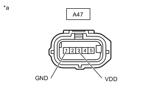
*a Front view of wire harness connector
(to Clutch Pedal Stroke Sensor Assembly)
Disconnect the clutch pedal stroke sensor assembly connector.
-
Turn the ignition switch to ON.
-
Measure the voltage according to the value(s) in the table below.
Standard Voltage Tester Connection Switch Condition Specified Condition A47-3 (VDD) - A47-1 (GND) Ignition switch ON 4.5 to 5.5 V Result Proceed to OK NG
NG 
CHECK HARNESS AND CONNECTOR (CLUTCH PEDAL STROKE SENSOR ASSEMBLY - ECM) Click here
OK
-
-
CHECK HARNESS AND CONNECTOR (CLUTCH PEDAL STROKE SENSOR ASSEMBLY - ECM)
-
Disconnect the C62 ECM connector.
-
Disconnect the A47 clutch pedal stroke sensor assembly connector.
-
Measure the resistance according to the value(s) in the table below.
Standard Resistance Tester Connection Condition Specified Condition A47-2 (OUT) - C62-119 (CLS) Always Below 1 Ω C62-119 (CLS) - Body ground Always 10 kΩ or higher Result Proceed to OK NG
NG
REPAIR OR REPLACE HARNESS OR CONNECTOR
OK
-
-
REPLACE CLUTCH PEDAL STROKE SENSOR ASSEMBLY
-
Replace the clutch pedal stroke sensor assembly.
-
for LHD
-
for RHD
Result Proceed to NEXT -
NEXT
-
-
CHECK WHETHER DTC OUTPUT RECURS (DTC P080512 OR P080514)
-
Connect the GTS to the DLC3.
-
Turn the ignition switch to ON.
-
Turn the GTS on.
-
Clear the DTCs.
Powertrain > Transmission > Clear DTCs -
Turn the ignition switch off and wait for at least 30 seconds.
-
Turn the ignition switch to ON.
-
Turn the GTS on.
-
Enter the following menus: Powertrain / Transmison / Trouble Codes.
Powertrain > Transmission > Trouble Codes -
Read the DTCs.
Result Result Proceed to DTC is not output A DTC P080512 or P080514 is output B
A
END
B
-
-
REPLACE ECM
-
Replace the ECM.
Result Proceed to NEXT
NEXT
PERFORM INITIALIZATION Click here
-
-
CHECK HARNESS AND CONNECTOR (CLUTCH PEDAL STROKE SENSOR ASSEMBLY - ECM)
-
Disconnect the C62 ECM connector.
-
Disconnect the A47 clutch pedal stroke sensor assembly connector.
-
Measure the resistance according to the value(s) in the table below.
Standard Resistance Tester Connection Condition Specified Condition A47-1 (GND) - C62-87 (E2CL) Always Below 1 Ω A47-3 (VDD) - C62-89 (VCCL) Always Below 1 Ω C62-87 (E2CL) - Body ground Always 10 kΩ or higher C62-89 (VCCL) - Body ground Always 10 kΩ or higher Result Proceed to OK NG
NG
REPAIR OR REPLACE HARNESS OR CONNECTOR
OK
-
-
REPLACE ECM
-
Replace the ECM.
Result Proceed to NEXT
NEXT
PERFORM INITIALIZATION Click here
-