SFI SYSTEM, Diagnostic DTC:P010012
| DTC Code | DTC Name |
|---|---|
| P010012 | Mass or Volume Air Flow Sensor "A" Circuit Short to Battery |
DESCRIPTION
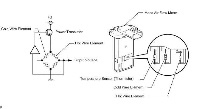
The mass air flow meter is a sensor that measures the intake air volume. The ECM uses this information to determine the ignition timing and fuel injection duration necessary for an optimal air fuel ratio. Inside the mass air flow meter are a hot wire element and a cold wire element which are exposed to the flow of intake air. The bridge circuit shown in the illustration outputs voltage to transmit information regarding heat loss of the hot wire element caused by air flow. Depending on the air flow, this voltage will change between approximately 0.2 V and 4.9 V. Based on this voltage, the ECM calculates the air flow to determine the ignition timing and fuel injection duration necessary for an optimal air fuel ratio.
Tech Tips
When P010012 is stored, the ECM enters fail-safe mode. During fail-safe mode, boost prohibited and the ignition timing is calculated by the ECM, according to the engine speed and throttle valve position. Fail-safe mode continues until a pass condition is detected, and the ignition switch is then turned off.
| DTC No. | Detection Item | DTC Detection Condition | Trouble Area | MIL | Memory | Note |
|---|---|---|---|---|---|---|
| P010012 | Mass or Volume Air Flow Sensor "A" Circuit Short to Battery | The mass air flow meter voltage is higher than 4.9 V for 3 seconds (1 trip detection logic). |
|
Comes on | DTC stored | SAE Code: P0103 |
Tech Tips
When this DTC is output, check the mass air flow in the Data List. Enter the following menus: Powertrain / Engine / Data List / All Data / Mass Air Flow Sensor.
| DTC No. | Mass Air Flow Sensor | Malfunction |
|---|---|---|
| P010012 | 271.0 gm/sec or more |
|
If the Data List values is normal it may be due to a temporary recovery from the malfunction condition. Check for intermittent problems.
MONITOR DESCRIPTION
If there is a defect or an open or short circuit in the mass air flow meter, the voltage level deviates from the normal operating range. The ECM interprets this deviation as a malfunction in the mass air flow meter circuit and stores this DTC.
Example:
When the sensor output voltage remains higher than 4.9 V for 3 seconds or more, the ECM stores this DTC.
MONITOR STRATEGY
| Frequency of Operation | Continuous |
CONFIRMATION DRIVING PATTERN
-
Connect the GTS to the DLC3.
-
Turn the ignition switch to ON.
-
Turn the GTS on.
-
Clear the DTCs (even if no DTCs are stored, perform the clear DTC procedure).
-
Turn the ignition switch off and wait for at least 30 seconds.
-
Turn the ignition switch to ON.
-
Turn the GTS on.
-
Wait 5 seconds or more.
-
Enter the following menus: Powertrain / Engine / Trouble Codes.
-
Read the pending DTCs.
Tech Tips
-
If a pending DTC is output, the system is malfunctioning.
-
If a pending DTC is not output, perform the following procedure.
-
-
Enter the following menus: Powertrain / Engine / Utility / All Readiness.
-
Input the DTC: P010012.
-
Check the DTC judgment result.
GTS Display Description NORMAL
-
DTC judgment completed
-
System normal
ABNORMAL
-
DTC judgment completed
-
System abnormal
INCOMPLETE
-
DTC judgment not completed
-
Perform driving pattern after confirming DTC enabling conditions
N/A
-
Unable to perform DTC judgment
-
Number of DTCs which do not fulfill DTC preconditions has reached ECU memory limit
Tech Tips
-
If the judgment result shows NORMAL, the system is normal.
-
If the judgment result shows ABNORMAL, the system has a malfunction.
-
If the judgment result shows INCOMPLETE or N/A, perform the Confirmation Driving Pattern and check the DTC judgment result again.
-
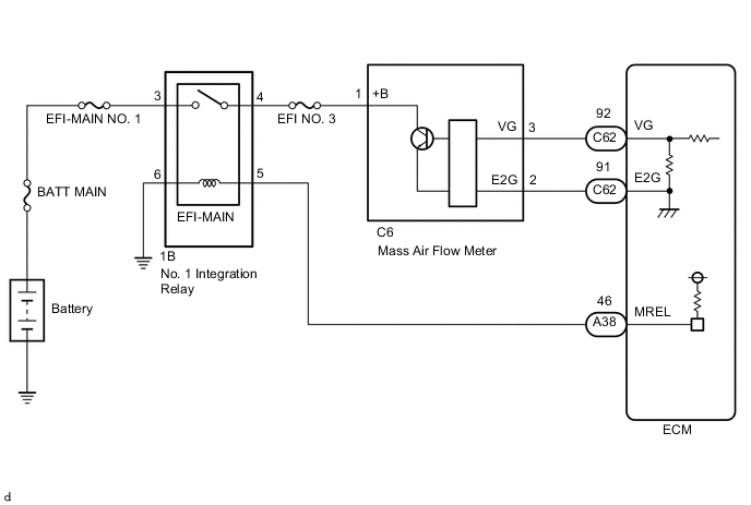
WIRING DIAGRAM
CAUTION / NOTICE / HINT
Note
Inspect the fuses for circuits related to this system before performing the following procedure.
Tech Tips
Read freeze frame data using the GTS. The ECM records vehicle and driving condition information as freeze frame data the moment a DTC is stored. When troubleshooting, freeze frame data can help determine if the vehicle was moving or stationary, if the engine was warmed up or not, if the air fuel ratio was lean or rich, and other data from the time the malfunction occurred.
PROCEDURE
-
CHECK HARNESS AND CONNECTOR (MASS AIR FLOW METER - ECM)
-
Disconnect the C6 mass air flow meter connector.
-
Disconnect the C62 ECM connector.
-
Measure the resistance according to the value(s) in the table below.
Standard Resistance Tester Connection Condition Specified Condition C6-2 (E2G) - C62-91 (E2G) Always Below 1 Ω C6-3 (VG) or C62-92 (VG) - Body ground and other terminals Always 10 kΩ or higher Result Proceed to OK NG
NG 
REPAIR OR REPLACE HARNESS OR CONNECTOR
OK 
-
-
CHECK HARNESS AND CONNECTOR (SENSOR GROUND)
-
Disconnect the C6 mass air flow meter connector.
-
Measure the resistance according to the value(s) in the table below.
Standard Resistance Tester Connection Condition Specified Condition C6-2 (E2G) - Body ground Always Below 1 Ω Result Proceed to OK NG
OK
REPLACE MASS AIR FLOW METER Click here
NG
REPLACE ECM Click here
-