SFI SYSTEM Turbocharger Noise
DESCRIPTION
Tech Tips
Turbocharger noise is classified into two types. These are whistling sound and chattering sound. During troubleshooting, first determine the type of noise.
| Type of Abnormal Noise | Outline of Abnormal Noise | Major Trouble Area |
|---|---|---|
| Whistling sound (airflow sound) | The whistling sound volume and pitch are proportional to the turbocharger or engine speed. The abnormal noise level becomes clear when the engine speed is increased. |
|
| Chattering sound (metallic sound) | The chattering sound pitch is lower than the whistling sound pitch. Has a comparatively constant pitch that is independent of the engine speed and vehicle speed. | Turbocharger Tech Tips
|
-
Faults and Symptoms of Gasoline Engine Components
Turbocharger system Main fault
-
Unstable turbocharger turbine shaft (interference, seizing, poor balance, etc.)
-
Poor installation or defective operation of the waste gate valve.
-
Poor installation or defective operation of the air by-pass valve assembly.
Symptom
-
High-pitched whistling sound
Tech Tips
The volume and pitch are proportional to the turbocharger speed.
-
Metallic sound due to looseness
Intake system Main fault Leak Symptom Abnormal noise during intake leak Transmission gears Symptom Gear noise
Tech Tips
The volume and pitch are proportional to the transmission gear speed.
-
PROCEDURE
-
CONFIRM CONDITION IN WHICH NOISE OCCURRED
-
Confirm with the customer the condition when noise occurred.
Tech Tips
To clearly understand the conditions in which the noise occurred, the items in the table below are useful.
Item Note Engine speed Engine speed range Vehicle speed Vehicle speed range Transaxle gear Which gear? Accelerator pedal position During acceleration or deceleration? Temperature
-
Ambient temperature
-
Engine temperature (cold, warmed up, etc.)
Road conditions
-
City or highway driving
-
Uphill or downhill
Noise level
-
Did the noise occur suddenly, or build gradually?
-
Has the noise gradually been getting louder?
Other symptoms
-
Lack of power
-
High fuel consumption, etc.
Noise recognition What made the customer determine that the sound was a malfunction? Result Proceed to NEXT -
NEXT 
-
-
CHECK DTC OUTPUT
-
Connect the GTS to the DLC3.
-
Start the engine.
-
Turn the GTS on.
-
Enter the following menus: Powertrain / Engine / Trouble Codes.
Powertrain > Engine > Trouble Codes -
Check DTCs.
Result Result Proceed to DTCs are not output A DTCs are output B Tech Tips
-
Check whether DTCs related to the turbo pressure sensor or atmospheric pressure sensor are output.
-
If a DTC related to the turbo pressure sensor or atmospheric pressure sensor is output, defective actuator control related to the turbocharger may be the cause of the noise.
-
B 
GO TO DTC CHART Click here
A
-
-
PERFORM SIMULATION TEST
-
Check whether the noise described by the customer occurs.
Tech Tips
If an abnormal noise is heard, check whether it matches the noise described by the customer.
-
If an abnormal noise is confirmed, determine which system emits it.
Result Result Proceed to Noise occurs (ticking or rattling (metallic sound) during idling) A Noise occurs (squealing (metallic sound) when driving) B Noise occurs (hissing (airflow sound) when driving) C Noise occurs (squeaking or chuffing (airflow sound) during deceleration) D Noise occurs (whistling or foghorn-like (airflow sound) during acceleration) E Noise occurs (whistling (airflow sound) during deceleration) F The noise described by the customer could not be confirmed. G
B 
CHECK TURBOCHARGER SUB-ASSEMBLY (INSPECT TURBINE SHAFT) Click here
C
CHECK TURBOCHARGER SUB-ASSEMBLY Click here
D
CHECK TURBOCHARGER SUB-ASSEMBLY (INSPECT AIR BY-PASS VALVE) Click here
E
REPLACE TURBOCHARGER SUB-ASSEMBLY Click here
F
CHECK GEAR NOISE Click here
G
EXPLAIN TO CUSTOMER THAT SOUND IS NORMAL Click here
A
-
-
CHECK TURBOCHARGER SUB-ASSEMBLY (INSPECT WASTE GATE VALVE ACTUATOR AND ACTUATOR ROD)
-
Check the installation condition of the E-ring on the link connection of the waste gate valve actuator and turbine housing.
-
Check the actuator rod for the waste gate valve actuator.
Tech Tips
-
Actuator rod wear may cause looseness leading to a chattering sound (metallic sound).
-
Compare with another vehicle of the same model which is not malfunctioning to see if there is any difference in the operation sound.
Result Result Proceed to No actuator rod malfunction A Actuator rod malfunction B -
B
REPLACE TURBOCHARGER SUB-ASSEMBLY (WASTE GATE VALVE ACTUATOR OR ACTUATOR ROD MALFUNCTION) Click here
A
-
-
CHECK TURBOCHARGER SUB-ASSEMBLY (INSPECT COMPRESSOR IMPELLER AND COMPRESSOR HOUSING)
-
Check for damage to the compressor impeller.
-
Check for interference between the compressor impeller and the compressor housing.
Result Result Proceed to No damage or interference A Damage or interference exists B
A
END (CAUSE CHECK EXCEPT THE TURBOCHARGER)
B
REPLACE TURBOCHARGER SUB-ASSEMBLY (COMPRESSOR IMPELLER OR COMPRESSOR HOUSING MALFUNCTION) Click here
-
-
CHECK TURBOCHARGER SUB-ASSEMBLY (INSPECT TURBINE SHAFT)
-
Check that the turbine shaft rotates smoothly, without catching.
-
Check for loose turbine mounting nuts and for axial play in the turbine shaft.
Tech Tips
If the turbine shaft catches or there is no play, seal failure due to seizure or improper operation due to accumulation of deposits is suspected.
Result Result Proceed to No turbine shaft malfunction A Turbine shaft malfunction B
B
REPLACE TURBOCHARGER SUB-ASSEMBLY (TURBINE SHAFT MALFUNCTION) Click here
A
-
-
CHECK TURBOCHARGER SUB-ASSEMBLY (INSPECT COMPRESSOR IMPELLER AND COMPRESSOR HOUSING)
-
Check for damage to the compressor impeller.
-
Check for interference between the compressor impeller and the compressor housing.
Result Result Proceed to No damage or interference A Damage or interference exists B
B
REPLACE TURBOCHARGER SUB-ASSEMBLY (COMPRESSOR IMPELLER OR COMPRESSOR HOUSING MALFUNCTION) Click here
A
-
-
CHECK TURBOCHARGER SUB-ASSEMBLY (INSPECT AIR BY-PASS VALVE)
-
Inspect the air by-pass valve assembly.
Tech Tips
-
The abnormal noise may be caused by defective operation of the air by-pass valve assembly.
-
If the previous checks find no malfunction, replace the turbocharger sub-assembly and determine if the noise improved.
Result Proceed to OK NG -
NG
REPLACE TURBOCHARGER SUB-ASSEMBLY (AIR BY-PASS VALVE MALFUNCTION) Click here
OK
-
-
REPLACE TURBOCHARGER SUB-ASSEMBLY
-
Replace the turbocharger sub-assembly.
Result Proceed to NEXT
NEXT
-
-
PERFORM SIMULATION TEST
-
Check that the abnormal noise has disappeared.
Result Proceed to NEXT
NEXT
END
-
-
CHECK TURBOCHARGER SUB-ASSEMBLY
-
Check for oil leaks and large carbon deposits around the connecting surfaces of the turbocharger sub-assembly.
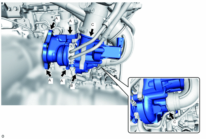
Tech Tips
If oil leaks or a large amount of carbon deposits exist, air leaks from the respective sealing surfaces may be causing the noise.
Result Result Proceed to An oil leak or large amount of carbon deposits does not exist. A A large amount of carbon deposits exist around the turbine housing, flange or gaskets in any of the areas (A) shown in the illustration. B Oil is leaking from between the sealing surfaces of the seal plate and compressor housing or bearing housing in the area (B) shown in the illustration. C Oil is leaking from the compressor housing in any of the areas (C) shown in the illustration. D
B
CHECK EXHAUST MANIFOLD CONVERTER SUB-ASSEMBLY Click here
C
REPLACE TURBOCHARGER SUB-ASSEMBLY Click here
D
CHECK AND REPAIR AIR TUBE OR HOSE CLAMP
A
-
-
REPLACE TURBOCHARGER SUB-ASSEMBLY
-
Replace the turbocharger sub-assembly.
Tech Tips
As the waste gate valve actuator or air by-pass valve is malfunctioning, it is necessary to replace the turbocharger sub-assembly.
Result Proceed to NEXT
NEXT
-
-
PERFORM SIMULATION TEST
-
Check that the abnormal noise has disappeared.
Result Proceed to NEXT
NEXT
END
-
-
CHECK EXHAUST MANIFOLD CONVERTER SUB-ASSEMBLY
-
Check for deformation or cracks in the mounting surfaces on the exhaust manifold converter sub-assembly and the turbine housing.
Tech Tips
Deformation or cracks on a mounting surface may allow exhaust gas to leak from the damaged position.
Standard No deformation or cracks on a mounting surface Result Result Proceed to No problem with the mounting surface A Deformation or cracks on the exhaust manifold converter sub-assembly mounting surface B Deformation or cracks on the turbine housing mounting surface C
B
REPLACE EXHAUST MANIFOLD CONVERTER SUB-ASSEMBLY Click here
C
REPLACE TURBOCHARGER SUB-ASSEMBLY Click here
A
-
-
REPLACE GASKET
-
Replace the exhaust gasket.
Result Proceed to NEXT
NEXT
-
-
PERFORM SIMULATION TEST
-
Check that the abnormal noise has disappeared.
Result Proceed to NEXT
NEXT
END
-
-
CHECK TURBOCHARGER SUB-ASSEMBLY (INSPECT AIR BY-PASS VALVE)
-
Inspect the air by-pass valve assembly.
Tech Tips
The abnormal noise may be caused by defective operation of the air by-pass valve assembly.
Result Proceed to OK NG
NG
REPLACE TURBOCHARGER SUB-ASSEMBLY (AIR BY-PASS VALVE MALFUNCTION) Click here
OK
-
-
READ VALUE USING GTS (ATMOSPHERIC PRESSURE)
-
Connect the GTS to the DLC3.
-
Turn the ignition switch to ON.
-
Enter the following menus: Powertrain / Engine / Data List / All Data / Atmospheric Pressure.
Powertrain > Engine > Data ListTester Display Atmospheric Pressure -
Using the table, read the normal atmospheric pressure value for the applicable altitude and temperature.
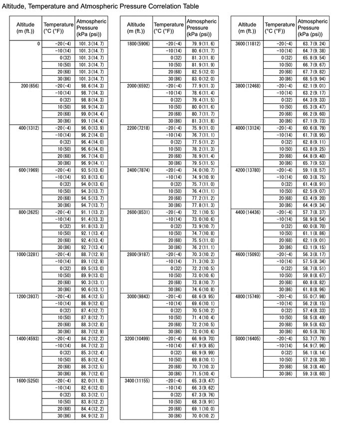
Tech Tips
-
Standard atmospheric pressure is approximately 101 kPa(abs) (15 psi(abs)).
-
For every 100 m (328 ft.) increase in altitude, atmospheric pressure drops by approximately 1 kPa (0.15 psi). This varies by weather.
-
-
Compare the Atmospheric pressure value in the Data List with the normal atmospheric value from the table.
Result Result Proceed to Other than the following A Difference between Atmospheric Pressure in the Data List and normal atmospheric pressure value is 10 kPa (1.45 psi) or more. B
B
REPLACE ECM Click here
A
-
-
CHECK NO. 1 TURBO PRESSURE SENSOR
-
On-vehicle inspect the No. 1 turbo pressure sensor.
Result Proceed to OK NG
OK
REPLACE ECM Click here
NG
REPLACE NO. 1 TURBO PRESSURE SENSOR Click here
-
-
REPLACE TURBOCHARGER SUB-ASSEMBLY
-
Replace the turbocharger sub-assembly.
Tech Tips
As the turbine shaft play is not appropriate or the compressor impeller is malfunctioning, it is necessary to replace the turbocharger sub-assembly.
Result Proceed to NEXT
NEXT
-
-
PERFORM SIMULATION TEST
-
Check that the abnormal noise has disappeared.
Result Proceed to NEXT
NEXT
END
-
-
CHECK GEAR NOISE
-
Check if gear noise is the source of the abnormal noise (not noise from the turbocharger).
Result Proceed to NEXT
NEXT
ELIMINATE THE CAUSE OF THE NOISE
-
-
EXPLAIN TO CUSTOMER THAT SOUND IS NORMAL
-
Explain to the customer that the sound described by the customer is not a malfunction.
Tech Tips
To convince the customer, it is helpful to drive the customer in a different vehicle.
Result Proceed to NEXT
NEXT
END
-