LIGHTING SYSTEM Power Source Circuit
DESCRIPTION
When the power switch is on (IG) or the operation conditions of the headlights are met, the main body ECU (multiplex network body ECU) supplies power to the No. 1 headlight ECU sub-assemblies via the No. 1 integration relay.
When the power switch is on (IG), the main body ECU (multiplex network body ECU) supplies power to the No. 1 headlight ECU sub-assemblies via the IG1-NO. 1 relay.
WIRING DIAGRAM

CAUTION / NOTICE / HINT
Note
-
Inspect the fuses for circuits related to this system before performing the following procedure.
-
Before replacing the main body ECU (multiplex network body ECU), refer to Service Bulletin.
PROCEDURE
-
INSPECT NO. 1 HEADLIGHT ECU SUB-ASSEMBLY (ECUB TERMINAL VOLTAGE)
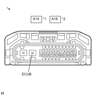
*1 No. 1 Headlight ECU Sub-assembly LH *2 No. 1 Headlight ECU Sub-assembly RH *a Component without harness connected
(No. 1 Headlight ECU Sub-assembly)
-
Disconnect the A15 No. 1 headlight ECU sub-assembly LH connector.
-
Disconnect the A16 No. 1 headlight ECU sub-assembly RH connector.
-
Measure the voltage according to the value(s) in the table below.
Standard Voltage No. 1 Headlight ECU Sub-assembly LH Tester Connection Condition Specified Condition A15-13 (ECUB) - Body ground Power switch on (IG) or light control switch in tail or head position 11 to 14 V No. 1 Headlight ECU Sub-assembly RH Tester Connection Condition Specified Condition A16-13 (ECUB) - Body ground Power switch on (IG) or light control switch in tail or head position 11 to 14 V Result Result Proceed to OK A NG (No. 1 Headlight ECU Sub-assembly LH) B NG (No. 1 Headlight ECU Sub-assembly RH) C
B 
INSPECT NO. 1 INTEGRATION RELAY Click here
C
INSPECT NO. 1 INTEGRATION RELAY Click here
A 
-
-
INSPECT NO. 1 HEADLIGHT ECU SUB-ASSEMBLY (IG TERMINAL VOLTAGE)
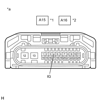
*1 No. 1 Headlight ECU Sub-assembly LH *2 No. 1 Headlight ECU Sub-assembly RH *a Component without harness connected
(No. 1 Headlight ECU Sub-assembly LH)
-
Measure the voltage according to the value(s) in the table below.
Standard Voltage No. 1 Headlight ECU Sub-assembly LH Tester Connection Condition Specified Condition A15-4 (IG) - Body ground Power switch on (IG) 11 to 14 V No. 1 Headlight ECU Sub-assembly RH Tester Connection Condition Specified Condition A16-4 (IG) - Body ground Power switch on (IG) 11 to 14 V Result Proceed to OK NG
NG 
REPAIR OR REPLACE HARNESS OR CONNECTOR
OK
-
-
CHECK HARNESS AND CONNECTOR (NO. 1 HEADLIGHT ECU SUB-ASSEMBLY - BODY GROUND)
-
Measure the resistance according to the value(s) in the table below.
Standard Resistance No. 1 Headlight ECU Sub-assembly LH Tester Connection Condition Specified Condition A15-12 (GND) - Body ground Always Below 1 Ω No. 1 Headlight ECU Sub-assembly RH Tester Connection Condition Specified Condition A16-12 (GND) - Body ground Always Below 1 Ω Result Proceed to OK NG
OK
PROCEED TO NEXT SUSPECTED AREA SHOWN IN PROBLEM SYMPTOMS TABLE Click here
NG
REPAIR OR REPLACE HARNESS OR CONNECTOR
-
-
INSPECT NO. 1 INTEGRATION RELAY
-
Remove the No. 1 integration relay.
-
Inspect the No. 1 integration relay.
Result Proceed to OK NG
NG
REPLACE NO. 1 INTEGRATION RELAY Click here
OK
-
-
CHECK HARNESS AND CONNECTOR (NO. 1 INTEGRATION RELAY - NO. 1 HEADLIGHT ECU SUB-ASSEMBLY LH)
-
Measure the resistance according to the value(s) in the table below.
Standard Resistance Tester Connection Condition Specified Condition 1B-1 - A15-13 (ECUB) Always Below 1 Ω 1B-1 or A15-13 (ECUB) - Body ground Always 10 kΩ or higher Result Proceed to OK NG
NG
REPAIR OR REPLACE HARNESS OR CONNECTOR
OK
-
-
CHECK HARNESS AND CONNECTOR (AUXILIARY BATTERY - NO. 1 INTEGRATION RELAY)
-
Measure the voltage according to the value(s) in the table below.
Standard Voltage Tester Connection Condition Specified Condition 1A-5 - Body ground Power switch off 11 to 14 V Result Proceed to OK NG
NG
REPAIR OR REPLACE HARNESS OR CONNECTOR
OK
-
-
CHECK HARNESS AND CONNECTOR (NO. 1 INTEGRATION RELAY - INSTRUMENT PANEL JUNCTION BLOCK ASSEMBLY)
-
Disconnect the 3F instrument panel junction block assembly connector.
-
Measure the resistance according to the value(s) in the table below.
Standard Resistance Tester Connection Condition Specified Condition 1B-2 - 3F-31 Always Below 1 Ω 1B-2 or 3F-31 - Body ground Always 10 kΩ or higher Result Proceed to OK NG
NG
REPAIR OR REPLACE HARNESS OR CONNECTOR
OK
-
-
INSPECT INSTRUMENT PANEL JUNCTION BLOCK ASSEMBLY
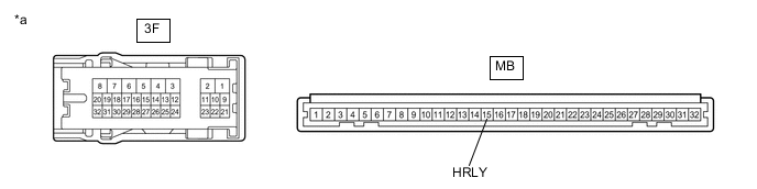
*a Component without harness connected
(Instrument Panel Junction Block Assembly)
- -
-
Remove the instrument panel junction block assembly.
-
Remove the main body ECU (multiplex network body ECU) from the instrument panel junction block assembly.
-
Measure the resistance according to the value(s) in the table below.
Standard Resistance Tester Connection Condition Specified Condition 3F-31 - MB-15 (HRLY) Always Below 1 Ω Result Proceed to OK NG
OK
REPLACE MAIN BODY ECU (MULTIPLEX NETWORK BODY ECU) Click here
NG
REPLACE INSTRUMENT PANEL JUNCTION BLOCK ASSEMBLY Click here
-
-
INSPECT NO. 1 INTEGRATION RELAY
-
Remove the No. 1 integration relay.
-
Inspect the No. 1 integration relay.
Result Proceed to OK NG
NG
REPLACE NO. 1 INTEGRATION RELAY Click here
OK
-
-
CHECK HARNESS AND CONNECTOR (NO. 1 INTEGRATION RELAY - NO. 1 HEADLIGHT ECU SUB-ASSEMBLY RH)
-
Measure the resistance according to the value(s) in the table below.
Standard Resistance Tester Connection Condition Specified Condition 1A-12 - A16-13 (ECUB) Always Below 1 Ω 1A-12 or A16-13 (ECUB) - Body ground Always 10 kΩ or higher Result Proceed to OK NG
NG
REPAIR OR REPLACE HARNESS OR CONNECTOR
OK
-
-
CHECK HARNESS AND CONNECTOR (AUXILIARY BATTERY - NO. 1 INTEGRATION RELAY)
-
Measure the voltage according to the value(s) in the table below.
Standard Voltage Tester Connection Condition Specified Condition 1B-8 - Body ground Power switch off 11 to 14 V Result Proceed to OK NG
NG
REPAIR OR REPLACE HARNESS OR CONNECTOR
OK
-
-
CHECK HARNESS AND CONNECTOR (NO. 1 INTEGRATION RELAY - MAIN BODY ECU (MULTIPLEX NETWORK BODY ECU))
-
Disconnect the I18 main body ECU (multiplex network body ECU) connector.
-
Measure the resistance according to the value(s) in the table below.
Standard Resistance Tester Connection Condition Specified Condition 1A-11 - I18-1 (DIM) Always Below 1 Ω 1A-11 or I18-1 (DIM) - Body ground Always 10 kΩ or higher Result Proceed to OK NG
OK
REPLACE MAIN BODY ECU (MULTIPLEX NETWORK BODY ECU) Click here
NG
REPAIR OR REPLACE HARNESS OR CONNECTOR
-