INTEGRATION RELAY REMOVAL
CAUTION / NOTICE / HINT
The necessary procedures (adjustment, calibration, initialization, or registration) that must be performed after parts are removed and installed, or replaced during No. 1 integration relay removal/installation are shown below.
| Replaced Part or Performed Procedure | Necessary Procedure | Effect/Inoperative Function when Necessary Procedure not Performed | Link |
|---|---|---|---|
| Disconnect cable from negative (-) auxiliary battery terminal | Memorize steering angle neutral point | Lane departure alert system (w/ Steering control) | |
| Intelligent clearance sonar system*1 | |||
| Simple intelligent parking assist system*1 | |||
| Pre-crash safety system | |||
| Adaptive high beam system | |||
| Parking assist monitor system | |||
| Initialize back door lock | Power door lock control system |
*1: When performing learning using the GTS.
PROCEDURE
-
PRECAUTION
Note
After turning the power switch off, waiting time may be required before disconnecting the cable from the negative (-) auxiliary battery terminal. Therefore, make sure to read the disconnecting the cable from the negative (-) auxiliary battery terminal notices before proceeding with work.
-
DISCONNECT CABLE FROM NEGATIVE AUXILIARY BATTERY TERMINAL
Note
When disconnecting the cable, some systems need to be initialized after the cable is reconnected.
-
REMOVE NO. 1 RELAY BLOCK COVER
-
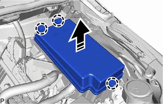

Remove in this Direction Disengage the 3 claws to remove the No. 1 relay block cover as shown in the illustration.
-
-
REMOVE NO. 1 INTEGRATION RELAY
-
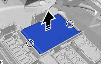
Remove in this Direction Disengage the 2 claws.
-
Pull the No. 1 integration relay as shown in the illustration.
Note
When pulling the No. 1 integration relay, take care not to damage it.
-
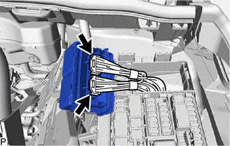
Disconnect the 2 connectors and remove the No. 1 integration relay.
Note
When pulling the No. 1 integration relay, take care not to damage it.
-