ELECTRONIC SHIFT LEVER SYSTEM, Diagnostic DTC:P272C73
| DTC Code | DTC Name |
|---|---|
| P272C73 | Park Pawl Motor Relay System Actuator Stuck Closed |
DESCRIPTION
The No. 1 integration relay (P-CON relay) is activated by voltage output from the hybrid vehicle control ECU and supplies power to the shift control actuator assembly (parking lock motor).
If the hybrid vehicle control ECU detects a malfunction of the No. 1 integration relay (P-CON relay), it stores this DTC.
| DTC No. | Detection Item | DTC Detection Condition | Trouble Area | Warning Indicate | Memory |
|---|---|---|---|---|---|
| P272C73 | Park Pawl Motor Relay System Actuator Stuck Closed | When the P-CON relay is off, voltage at terminals MUA, MVA or MWA of the hybrid vehicle control ECU is 6 V or more for 0.064 seconds or more. |
|
|
DTC stored |
CONFIRMATION DRIVING PATTERN
Tech Tips
After repairs have been completed, clear the DTCs and then check that the vehicle has returned to normal by performing the following All Readiness check procedure.
-
Turn the power switch on (IG).
-
With the brake pedal depressed, select neutral (N).
-
Push the P position switch (transmission shift main switch).
PROCEDURE
-
CHECK SHIFT CONTROL ACTUATOR ASSEMBLY (SHIFT CONTROL ACTUATOR ASSEMBLY POWER SOURCE CIRCUIT)
-
Disconnect the C2 shift control actuator assembly connector.
-

*a Front view of wire harness connector
(to Shift Control Actuator Assembly)
Measure the voltage according to the value(s) in the table below.
Standard Voltage Tester Connection Condition Specified Condition C2-2 (BMA) - Body ground Power switch off Below 1 V -
Reconnect the C2 shift control actuator assembly connector.
Result Proceed to OK NG
NG 
INSPECT NO. 1 INTEGRATION RELAY (P-CON RELAY) Click here
OK 
-
-
CHECK HARNESS AND CONNECTOR (HYBRID VEHICLE CONTROL ECU - SHIFT CONTROL ACTUATOR ASSEMBLY)
-
Disconnect the A41 hybrid vehicle control ECU connector.
-
Disconnect the C2 shift control actuator assembly connector.
-
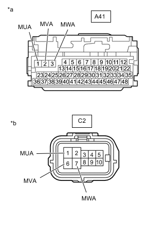
*a Front view of wire harness connector
(to Hybrid Vehicle Control ECU)
*b Front view of wire harness connector
(to Shift Control Actuator Assembly)
Measure the resistance according to the value(s) in the table below.
Standard Resistance (Check for Short) Tester Connection Condition Specified Condition A41-1 (MUA) or C2-1 (MUA) - Body ground and other terminals Power switch off 10 kΩ or higher A41-2 (MVA) or C2-6 (MVA) - Body ground and other terminals Power switch off 10 kΩ or higher A41-3 (MWA) or C2-7 (MWA) - Body ground and other terminals Power switch off 10 kΩ or higher -
Reconnect the C2 shift control actuator assembly connector.
-
Reconnect the A41 hybrid vehicle control ECU connector.
Result Proceed to OK NG
OK 
REPLACE HYBRID VEHICLE CONTROL ECU Click here
NG
REPAIR OR REPLACE HARNESS OR CONNECTOR
-
-
INSPECT NO. 1 INTEGRATION RELAY (P-CON RELAY)
Result Proceed to OK NG
NG
REPLACE NO. 1 INTEGRATION RELAY (P-CON RELAY) Click here
OK
-
CHECK HARNESS AND CONNECTOR (HYBRID VEHICLE CONTROL ECU - P-CON RELAY)
-
Disconnect the A41 hybrid vehicle control ECU connector.
-
Disconnect the 1B No. 1 integration relay connector.
-

*a Front view of wire harness connector
(to Hybrid Vehicle Control ECU)
Measure the resistance according to the value(s) in the table below.
Standard Resistance (Check for Short) Tester Connection Condition Specified Condition A41-15 (BMA) - Body ground and other terminals Power switch off 10 kΩ or higher -
Reconnect the 1B No. 1 integration relay connector.
-
Reconnect the A41 hybrid vehicle control ECU connector.
Result Proceed to OK NG
NG
REPAIR OR REPLACE HARNESS OR CONNECTOR
OK
-
-
CHECK HARNESS AND CONNECTOR (SHIFT CONTROL ACTUATOR ASSEMBLY - P-CON RELAY)
-
Disconnect the C2 shift control actuator assembly connector.
-
Disconnect the 1B No. 1 integration relay connector.
-
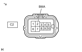
*a Front view of wire harness connector
(to Shift Control Actuator Assembly)
Measure the resistance according to the value(s) in the table below.
Standard Resistance (Check for Short) Tester Connection Condition Specified Condition C2-2 (BMA) - Body ground and other terminals Power switch off 10 kΩ or higher -
Reconnect the 1B No. 1 integration relay connector.
-
Reconnect the C2 shift control actuator assembly connector.
Result Proceed to OK NG
OK
CHECK FOR INTERMITTENT PROBLEMS Click here
NG
REPAIR OR REPLACE HARNESS OR CONNECTOR
-