INSTRUMENT PANEL SAFETY PAD REMOVAL
CAUTION / NOTICE / HINT
CAUTION:
Some of these service operations affect the SRS airbag system. Read the precautionary notices concerning the SRS airbag system before servicing.
Tech Tips
-
Use the same procedure for RHD and LHD vehicles.
-
The procedure listed below is for LHD vehicles.
PROCEDURE
-
TABLE OF BOLT, SCREW, NUT
Tech Tips
-
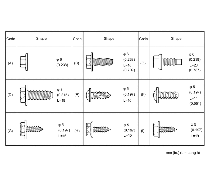
All bolts, screws and nuts relevant to installing and removing the instrument panel are shown along with their alphabet codes in the table below.
-
-
PRECAUTION
Note
After turning the power switch off, waiting time may be required before disconnecting the cable from the negative (-) auxiliary battery terminal. Therefore, make sure to read the disconnecting the cable from the negative (-) auxiliary battery terminal notice before proceeding with work.
-
CUSTOMIZE POWER TILT AND POWER TELESCOPIC STEERING COLUMN SYSTEM
Tech Tips
If the AUTO-AWAY is not disabled before disconnecting the negative (-) auxiliary battery terminal, the steering column cover will be difficult to remove. So, disable the AUTO-AWAY before disconnecting the negative (-) auxiliary battery terminal.
-
REMOVE FRONT SEAT ASSEMBLY RH (for LHD)
-
REMOVE FRONT SEAT ASSEMBLY LH (for RHD)
-
REMOVE FRONT DOOR SCUFF PLATE LH (for LHD)
-
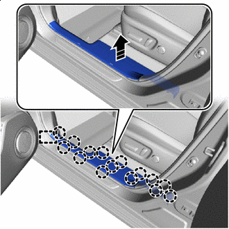

Remove in this Direction Disengage the claws and guide to remove the front door scuff plate LH as shown in the illustration.
-
-
REMOVE FRONT DOOR SCUFF PLATE RH (for RHD)
-
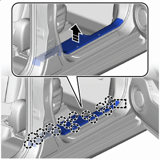
Remove in this Direction Disengage the claws and guide to remove the front door scuff plate RH as shown in the illustration.
-
-
REMOVE NO. 2 INSTRUMENT PANEL UNDER COVER SUB-ASSEMBLY
-
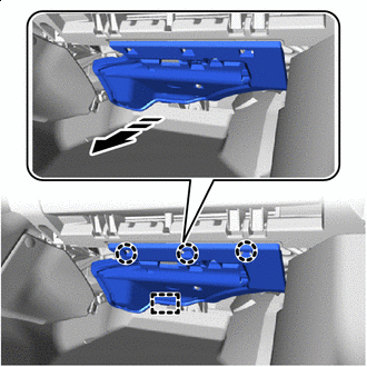
Remove in this Direction for LHD:
-
Disengage the claws and guide to remove the No. 2 instrument panel under cover sub-assembly as shown in the illustration.
-
Disconnect the connector and disengage the clamp.
-
-
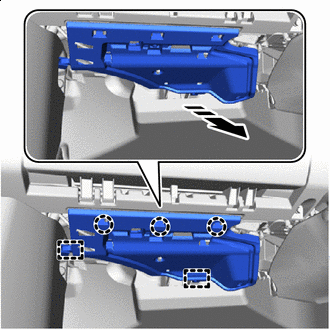
Remove in this Direction for RHD:
-
Disengage the claws and guides to remove the No. 2 instrument panel under cover sub-assembly as shown in the illustration.
-
Disconnect the connector and disengage the clamp.
-
-
-
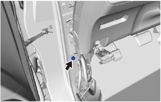
REMOVE COWL SIDE TRIM BOARD LH
-
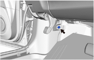
Remove the clip.
-
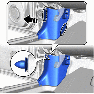

Place Hands Here Remove in this Direction Disengage the clip to remove the cowl side trim board LH as shown in the illustration.
-
-
REMOVE COWL SIDE TRIM BOARD RH
Tech Tips
Use the same procedure as for the LH side.
-
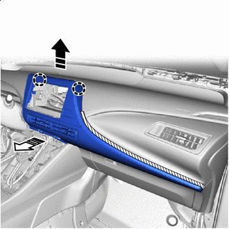
REMOVE NO. 1 INSTRUMENT PANEL SPEAKER PANEL SUB-ASSEMBLY
-
Remove in this Direction As shown in the illustration, use moulding remover A to raise up the No. 1 instrument panel speaker panel sub-assembly.
-
Lift up in the direction shown by the arrow in the illustration to disengage the claws and clips.
-
Remove in this Direction Disengage the guides to remove the No. 1 instrument panel speaker panel sub-assembly as shown in the illustration.
-
-
REMOVE NO. 2 INSTRUMENT PANEL SPEAKER PANEL SUB-ASSEMBLY
Tech Tips
Use the same procedure as for the No. 1 side.
-
REMOVE FRONT NO. 2 SPEAKER ASSEMBLY
-
REMOVE NO. 1 INSTRUMENT PANEL CUSHION
-
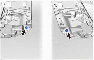
*a LH Side *b RH Side Remove the 2 screws <H>.
-
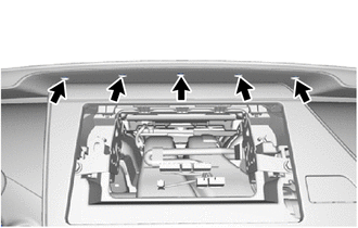
Remove the 5 clips.
-
Place Hands Here Remove in this Direction Disengage the clips and claws to remove the No. 1 instrument panel cushion.
-
-
DISCONNECT FRONT DOOR OPENING TRIM WEATHERSTRIP LH
-
Disconnect the front door opening trim weatherstrip LH.
-
-
DISCONNECT FRONT DOOR OPENING TRIM WEATHERSTRIP RH
Tech Tips
Use the same procedure as for the LH side.
-
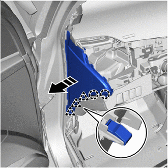
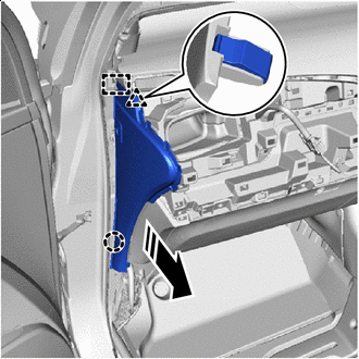
REMOVE FRONT PILLAR GARNISH LH
-
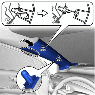
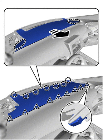
Place Hands Here Remove in this Direction Disconnect the 2 front pillar garnish clips from the front pillar garnish LH as shown in the illustration.
-
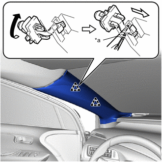
*a Protective Tape Using needle-nose pliers with their tips ends wrapped in protective tape, turn the front pillar garnish clip clockwise 90°and remove it from the front pillar garnish LH.
Note
-
If the front pillar garnish clip is not removed from the vehicle and has no damage, the clip can be reused.
-
If the front pillar garnish clip is removed from the vehicle, replace it with a new one.
-
-
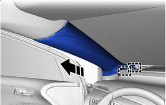
Remove in this Direction Disengage the guides to remove the front pillar garnish LH as shown in the illustration.
-
Remove the 2 front pillar garnish clips from the body.
-
Protect the curtain shield airbag:
-
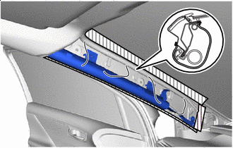
*1 CURTAIN SHIELD AIRBAG 
Packing Tape Cover the airbag with cloth or similar and fasten it with packing tape as shown in the illustration.
Note
Protect curtain shield airbag as soon as the front pillar garnish LH is removed.
-
-
-
REMOVE FRONT PILLAR GARNISH RH
Tech Tips
Use the same procedure as for the LH side.
-
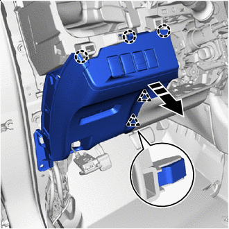
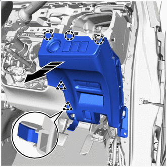
REMOVE NO. 1 INSTRUMENT PANEL UNDER COVER SUB-ASSEMBLY
-
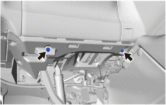
for LHD:
-
Remove the 2 screws <H> or <I>.
-
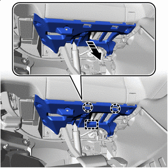
Remove in this Direction Disengage the claws and guide to remove the No. 1 instrument panel under cover sub-assembly as shown in the illustration.
-
Disconnect the connectors and disengage the clamp.
-
-
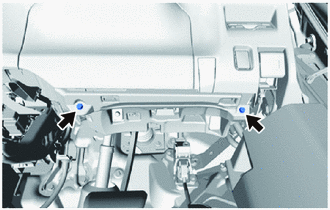
for RHD:
-
Remove the 2 screws <H> or <I>.
-
Remove in this Direction Disengage the claws and guide to remove the No. 1 instrument panel under cover sub-assembly as shown in the illustration.
-
Disconnect the connectors and disengage the clamp.
-
-
-
REMOVE INTEGRATION CONTROL AND PANEL ASSEMBLY
-
REMOVE INSTRUMENT CENTER UPPER CLUSTER FINISH PANEL
-
for LHD:
-
Using a moulding remover A, disengage the claws to open the cover.
-
Remove the screw <H> or <I>.
-
Place Hands Here Remove in this Direction Disengage the claw and clips to remove the instrument center upper cluster finish panel as shown in the illustration.
-
-
Place Hands Here Remove in this Direction for RHD:
-
Disengage the claw and clips to remove the instrument center upper cluster finish panel as shown in the illustration.
-
Disconnect the connector and disengage the clamp.
-
-
-
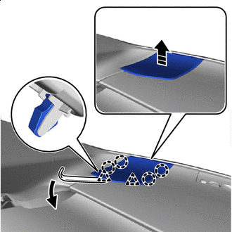
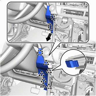
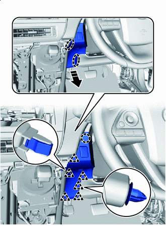
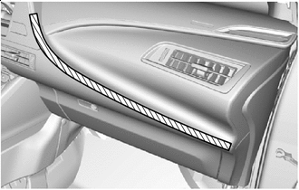
REMOVE INSTRUMENT CENTER PANEL REGISTER ASSEMBLY
-
Open the glove compartment door assembly.
-
Protective Tape Apply protective tape as shown in the illustration.
-
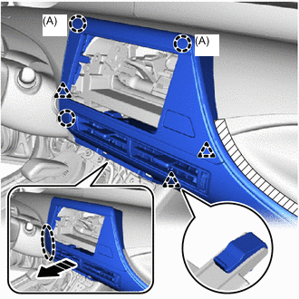
Place Hands Here Remove in this Direction Disengage the claws and clips as shown in the illustration.
Note
The claws (A) in the illustration are 2-stage, so in this step, disengage the end portions.
-
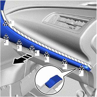
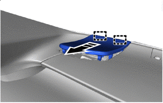
Remove in this Direction Disengage the clips and claws in the order shown in the illustration.
-
Remove in this Direction (1) 
Remove in this Direction (2) Lift up in the direction shown by the arrow (1) in the illustration, pull in the direction shown by the arrow (2) in the illustration to disengage the clips, and remove the instrument center panel register assembly.
Note
The claws in the illustration are 2-stage, so in this step, disengage the tips.
-
Disconnect the connector.
-
-
REMOVE RADIO RECEIVER ASSEMBLY
-
REMOVE LOWER STEERING COLUMN COVER
-
REMOVE UPPER STEERING COLUMN COVER
-
REMOVE NO. 1 INSTRUMENT PANEL REGISTER ASSEMBLY
-
Place Hands Here Remove in this Direction Pull in the direction shown by the arrow in the illustration.
-
Disengage the claws, clips and guides in the order shown in the illustration to remove it.
-
for LHD:
-
Disconnect the connector.
-
-
-
REMOVE INSTRUMENT SIDE PANEL LH (for LHD)
-
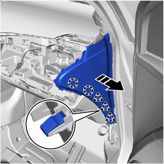
Remove in this Direction Disengage the claws and clips as shown in the illustration.
-
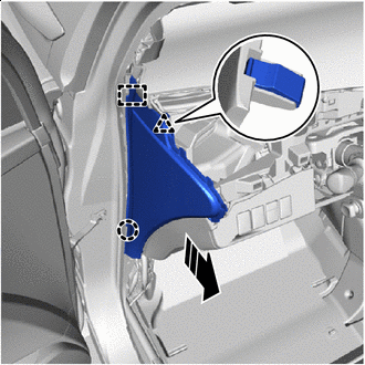
Remove in this Direction Disengage the claw, clip and guide as shown in the illustration to remove it.
-
-
REMOVE INSTRUMENT SIDE PANEL RH (for RHD)
-

Remove in this Direction Disengage the claws and clips as shown in the illustration.
-
Remove in this Direction Disengage the claw, clip and guide as shown in the illustration to remove it.
-
-
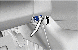
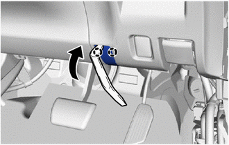
DISCONNECT HOOD LOCK CONTROL LEVER SUB-ASSEMBLY
-
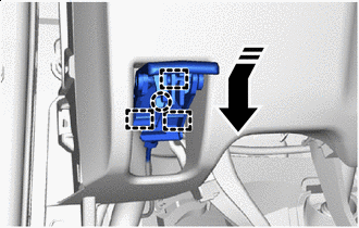
Remove in this Direction Disengage the claw and guides to disconnect the hood lock control lever sub-assembly as shown in the illustration.
-
-
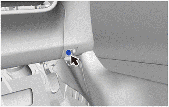
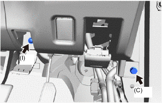
REMOVE INSTRUMENT PANEL LOWER FINISH PANEL
-
for LHD:
-
Remove the bolt <C>.
-
Remove in this Direction Disengage the claws and clips to remove the instrument panel lower finish panel as shown in the illustration.
-
Disconnect the connectors and disengage the clamp.
-
-
for RHD:
-
Using a molding remover A, disengage the claws to open the cover.
-
Remove the screw <I> and bolt <C>.
-
Remove in this Direction Disengage claws and clips to remove the instrument panel lower finish panel as shown in the illustration.
-
Disconnect the connector and disengage the clamp.
-
-
-
REMOVE NO. 2 INSTRUMENT PANEL REGISTER ASSEMBLY
-
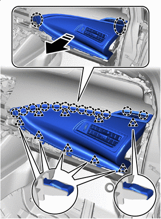
Place Hands Here Remove in this Direction Disengage the clips and claws to remove the No. 2 instrument panel register assembly.
-
-
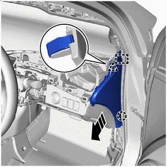
REMOVE INSTRUMENT SIDE PANEL RH (for LHD)
-
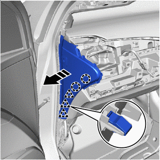
Remove in this Direction Disengage the claws and clips as shown in the illustration.
-
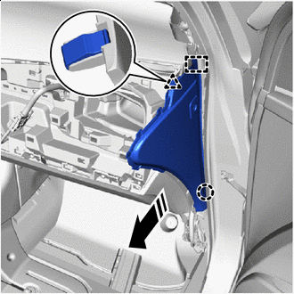
Remove in this Direction Disengage the claw, clip and guide as shown in the illustration to remove it.
-
Disconnect the connector.
-
-
REMOVE INSTRUMENT SIDE PANEL LH (for RHD)
-
Remove in this Direction Disengage the claws and clips as shown in the illustration.
-
Remove in this Direction Disengage the claw, clip and guide as shown in the illustration to remove it.
-
Disconnect the connector.
-
-
REMOVE GLOVE COMPARTMENT DOOR ASSEMBLY
-
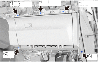
*1 (H) or (I) Remove the 2 bolts <C> and 3 screws <H> or <I>.
-
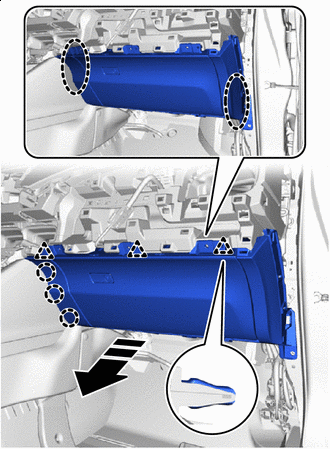
Place Hands Here Remove in this Direction Disengage the claws and clips to remove the glove compartment door assembly as shown in the illustration.
-
Disconnect the connector.
-
-
REMOVE FRONT CONSOLE BOX COVER
-
REMOVE CONSOLE COMPARTMENT BOX ASSEMBLY
-
REMOVE STEREO JACK ADAPTER ASSEMBLY
-
REMOVE MOBILE WIRELESS CHARGER CRADLE ASSEMBLY
-
REMOVE NO. 6 CONSOLE BOX RETAINER
-
REMOVE FRONT NO. 1 CONSOLE BOX INSERT
-
REMOVE FRONT NO. 2 CONSOLE BOX INSERT
Tech Tips
Use the same procedure as for the No. 1 side.
-
REMOVE NO. 2 CONSOLE BOX DUCT
-
REMOVE NO. 1 CONSOLE BOX DUCT
-
REMOVE CONSOLE REAR END PANEL SUB-ASSEMBLY
-
REMOVE NO. 4 CONSOLE BOX DUCT
-
REMOVE REAR CONSOLE BOX SUB-ASSEMBLY
-
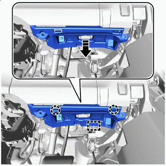
REMOVE LOWER INSTRUMENT PANEL ASSEMBLY
-
Remove the 2 clips.
-
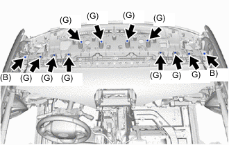
Remove the 2 bolts <B> and 10 screws <G>.
-
Disconnect the 2 connectors.
-
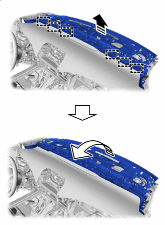
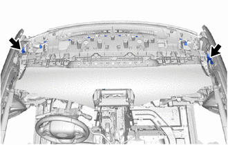
Remove in this Direction (1) Remove in this Direction (2) Lift up in the direction shown by the arrow (1) in the illustration to disengage the guides.
-
Pull in the direction shown by the arrow (2) in the illustration to remove the lower instrument panel assembly.
-
-
REMOVE COMBINATION METER ASSEMBLY
-
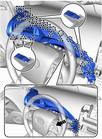
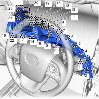
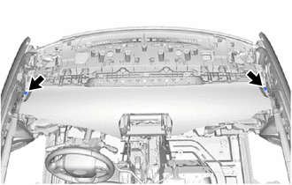
REMOVE UPPER INSTRUMENT PANEL SUB-ASSEMBLY
-
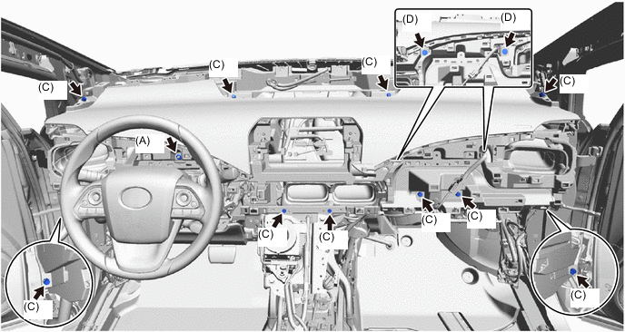
Remove the 10 bolts <C>, 2 bolts <D> and nut <A>.
-
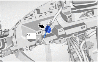
*a Slider Slide the slider to disconnect the instrument panel wire.
-
Disconnect the connectors and disengage the clamps.
-
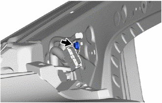
Remove the bolt.
-
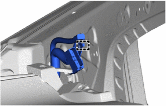
Disengage the guide to disconnect the No. 3 antenna cord sub-assembly.
-
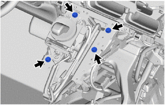
Remove the 4 bolts <D>.
-
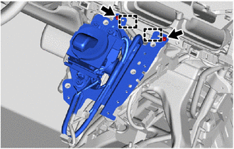
Remove the 2 screws <H>.
-
Disengage the guides to disconnect the shift lever with bracket.
-
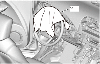
*a Cloth To prevent scratches or damage to the parts during removal, place cloth in the location shown in the illustration.
-
Remove the upper instrument panel sub-assembly:
-
Remove the upper instrument panel sub-assembly as shown in the illustration.
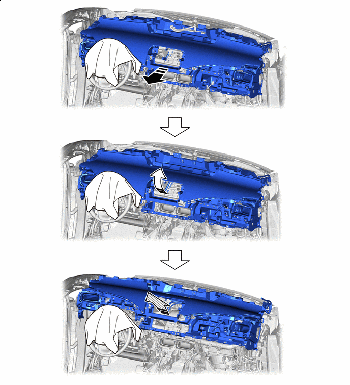
Remove in this Direction (1) Remove in this Direction (2) 
Remove in this Direction (3) - -
-
-