COMPRESSOR REMOVAL
CAUTION / NOTICE / HINT
CAUTION:
-
This vehicle has contains high voltage circuits standardized with orange colored wiring and connectors, so follow the instructions in this manual to perform the procedures correctly.
-
If the correct procedures are not followed according to the instructions in this manual, there is a danger of electric shock from the high voltage circuits.
-

Be sure to wear insulating gloves when working on high voltage wiring or components.
-
If work is performed without wearing insulating gloves, there is a danger of electric shock.
-
*: If the Rear View Monitor screen displays "System Initializing", perform steering sensor zero-point calibration.
PROCEDURE
-
CAUTION
Note
After turning the power switch off, waiting time may be required before disconnecting the cable from the negative (-) auxiliary battery terminal. Therefore, make sure to read the disconnecting the cable from the negative (-) auxiliary battery terminal notices before proceeding with work.
-
RECOVER REFRIGERANT FROM REFRIGERATION SYSTEM
-
REMOVE SERVICE PLUG GRIP (for EV)
-
REMOVE FC STACK SERVICE PLUG GRIP
-
REMOVE INVERTER COVER
-
REMOVE INVERTER TERMINAL COVER
-
CHECK TERMINAL VOLTAGE
-
INSTALL INVERTER TERMINAL COVER
-
REMOVE FRONT BUMPER ABSORBER LOWER
-
REMOVE AIR CLEANER INLET
-
REMOVE AIR CLEANER ASSY WITH ELEMENT
-
REMOVE AIR CLEANER HOSE ASSEMBLY
-
DISCONNECT NO. 1 COOLER REFRIGERANT DISCHARGE HOSE
-
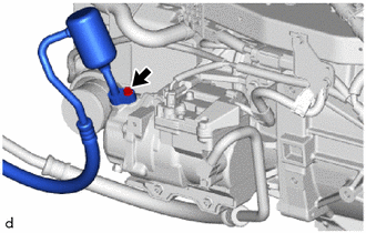
Remove the bolt to disconnect the No. 1 cooler refrigerant discharge hose from the with motor compressor assembly.
-
Remove the O-ring from the No. 1 cooler refrigerant discharge hose.
Note
Wrap protective tape around the connecting portions of the disconnected No. 1 cooler refrigerant discharge hose and with motor compressor assembly to prevent contamination by foreign matter or water droplets.
-
-
DISCONNECT SUCTION HOSE SUB-ASSEMBLY
-
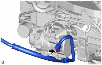
Remove the bolt to disconnect the suction hose sub-assembly from the with motor compressor assembly.
-
Remove the O-ring from the suction hose sub-assembly.
Note
Wrap protective tape around the connecting portions of the disconnected suction hose sub-assembly and the with motor compressor assembly to prevent contamination by foreign matter or water droplets.
-
-
REMOVE WITH MOTOR COMPRESSOR ASSEMBLY
-
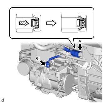
As shown in the illustration, release the green lock of connector A and disconnect the connector.
CAUTION:
Make sure to wear insulating gloves.
Note
Insulate the disconnected terminals and connector with insulating tape.
-
Disconnect connector B.
-
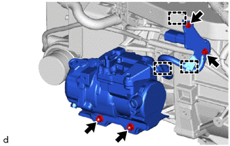
Remove the bolt to separate the ground wire.
-
Remove the bolt to separate the cooler bracket.
-
Remove the 2 nuts.
-
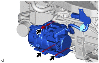
Using an E8 ''TORX'' socket wrench, remove the 2 stud bolts and bolt and with motor compressor assembly.
-
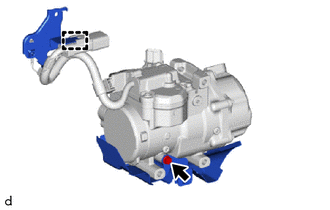
Remove the bolt and cooler compressor bracket.
-
Disengage the clamp to remove the cooler bracket.
-