AIR CONDITIONING SYSTEM, Diagnostic DTC:B1475/75
| DTC Code | DTC Name |
|---|---|
| B1475/75 | A/C Inverter Cooling / Heating System Malfunction |
DESCRIPTION
The temperature sensor of the compressor with motor assembly detects the A/C inverter temperature.
If the temperature exceeds the maximum, operation of the compressor with motor assembly will be stopped, and this DTC will be stored.
| DTC No. | Detection Item | DTC Detection Condition | Trouble Area | Memory |
|---|---|---|---|---|
| B1475/75 | A/C Inverter Cooling / Heating System Malfunction | Any of the following conditions is met:
|
|
Memorized |
| Vehicle Condition | ||||
|---|---|---|---|---|
| Pattern 1 | Pattern 2 | Pattern 3 | ||
| Diagnosis Condition | Power switch on (READY) | ○ | ○ | ○ |
| Malfunction Status | Temperature of the A/C inverter is outside the specified range (temperature is too high) | ○ | - | - |
| There is an open to ground in the temperature sensor circuit | - | ○ | - | |
| There is an short to ground in the temperature sensor circuit | - | - | ○ | |
| Detection Time | - | - | - | |
| Number of Trips | 1 trip | 1 trip | 1 trip | |
Tech Tips
DTC will be output when conditions for either of the patterns in the table above are met.
CAUTION / NOTICE / HINT
CAUTION:
-
Wear insulated gloves and pull out the service plug grip before inspection as procedures may require disconnecting high-voltage connectors. Carry the removed service plug in your pocket to prevent other technicians from accidentally reconnecting it while you are servicing the vehicle.
-
Do not touch the high-voltage connectors or terminals for 10 minutes after the service plug grip is removed.
Note
-
After turning the power switch off, waiting time may be required before disconnecting the cable from the negative (-) auxiliary battery terminal. Therefore, make sure to read the disconnecting the cable from the negative (-) auxiliary battery terminal notices before proceeding with work.
-
The hybrid control system and air conditioning system output DTCs separately. Perform troubleshooting for the hybrid control system first if DTCs from these systems are output simultaneously.
PROCEDURE
-
CHECK CAN COMMUNICATION SYSTEM
-
Using the GTS, check if the CAN communication system is functioning normally.
for LHD: Click here
for RHD: Click here
Result Result Proceed to CAN communication system DTCs are not output A CAN communication system DTCs are output (for LHD) B CAN communication system DTCs are output (for RHD) C
B 
GO TO CAN COMMUNICATION SYSTEM Click here
C
GO TO CAN COMMUNICATION SYSTEM Click here
A 
-
-
PERFORM ACTIVE TEST USING GTS
-
Connect the GTS to the DLC3.
-
Turn the power switch on (IG).
-
Turn the GTS on.
-
Enter the following menus: Powertrain / FC / Active Test.
-
Check the operation by referring to the table below.
Powertrain > FC > Active TestTester Display Measurement Item Control Range Diagnostic Note Radiator Fan1 Drive the cooling fan controller with motor (for fan side) 0 to 100% - Radiator Fan2 Drive the cooling fan controller with motor (for No. 2 fan side) 0 to 100% -
Powertrain > FC > Active TestTester Display Radiator Fan1
Powertrain > FC > Active TestTester Display Radiator Fan2 OK Cooling fan controller with motor operates smoothly. Result Proceed to OK NG
NG
GO TO COOLING FAN SYSTEM Click here
OK
-
-
CHECK REFRIGERANT PRESSURE
-
Install a manifold gauge set.
-
Turn the power switch on (READY).
-
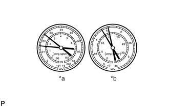
*a LO *b HI Read the manifold gauge pressure when the following conditions are met.
-
Prepare the vehicle according to the table below.
Item Condition Vehicle doors Fully open Temperature setting MAX COLD Blower speed HI A/C switch On Recirculation/fresh switch RECIRCULATION Interior temperature 25 to 35°C (77 to 95°F)
Standard Pressure Low pressure side 150 to 250 kPa (1.5 to 2.5 kgf/cm2, 22 to 36 psi) High pressure side 1370 to 1570 kPa (14 to 16 kgf/cm2, 199 to 228 psi) Result Proceed to OK NG -
NG
CHARGE REFRIGERANT Click here
OK
-
-
CHECK FOR DTC
-
Clear the DTCs.
Body Electrical > Air Conditioner > Clear DTCs -
Turn the power switch on (READY).
-
Prepare the vehicle according to the table below.
Item Condition Blower speed HI A/C switch On Temperature setting MAX COLD -
Check for DTCs.
Body Electrical > Air Conditioner > Trouble CodesResult Result Proceed to DTC B1475/75 is not output A DTC B1475/75 is output B Note
When ambient temperature is high, the compressor with motor assembly may automatically stop to protect the inverter circuit, and DTC B1475/75 may be stored.
A
USE SIMULATION METHOD TO CHECK Click here
B
REPLACE COMPRESSOR WITH MOTOR ASSEMBLY Click here
-