AIR CONDITIONING SYSTEM, Diagnostic DTC:B14C4
| DTC Code | DTC Name |
|---|---|
| B14C4 | Electric Water Heater Circuit |
DESCRIPTION
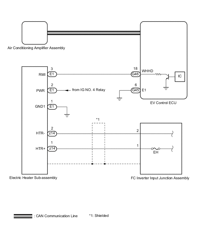
The air conditioning amplifier assembly uses the target blower temperature to calculate the target water temperature, and selects the electric heater sub-assembly drive level based on the water temperature sensor value.
The air conditioning amplifier assembly sends the drive level to the EV control ECU via the CAN communication system, and the EV control ECU drives the electric heater sub-assembly.
| DTC No. | Detection Item | DTC Detection Condition | Trouble Area | Memory |
|---|---|---|---|---|
| B14C4 | Electric Water Heater Circuit | The air conditioning amplifier assembly stores this DTC if it detects a malfunction in the electric heater sub-assembly. |
|
Memorized |
WIRING DIAGRAM
CAUTION / NOTICE / HINT
CAUTION:
-
Wear insulated gloves and pull out the service plug grip before inspection as procedures may require disconnecting high-voltage connectors. Carry the removed service plug in your pocket to prevent other technicians from accidentally reconnecting it while you are servicing the vehicle.
-
Do not touch the high-voltage connectors or terminals for 10 minutes after the service plug grip is removed.
Note
-
Inspect the fuses for circuits related to this system before performing the following procedure.
-
After turning the power switch off, waiting time may be required before disconnecting the cable from the negative (-) auxiliary battery terminal. Therefore, make sure to read the disconnecting the cable from the negative (-) auxiliary battery terminal notices before proceeding with work.
-
The hybrid control system and air conditioning system output DTCs separately. Perform troubleshooting for the hybrid control system first if DTCs from these systems are output simultaneously.
-
The Vehicle Identification Number (VIN) or frame number must be input into a replacement EV control ECU.
PROCEDURE
-
CHECK HARNESS AND CONNECTOR (ELECTRIC HEATER SUB-ASSEMBLY - POWER SOURCE CIRCUIT)
CAUTION:
Do not disconnect the connector on the high-voltage side.
-
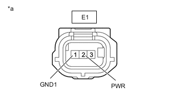
*a Front view of wire harness connector
(to Electric Heater Sub-assembly)
Disconnect the electric heater sub-assembly connector.
-
Measure the resistance according to the value(s) in the table below.
Standard Resistance Tester Connection Condition Specified Condition E1-1 (GND1) - Body ground Always Below 1 Ω -
Measure the voltage according to the value(s) in the table below.
Standard Voltage Tester Connection Switch Condition Specified Condition E1-2 (PWR) - Body ground Power switch on (IG) 11 to 14 V E1-2 (PWR) - Body ground Power switch off Below 1 V Result Proceed to OK NG
NG 
REPAIR OR REPLACE HARNESS OR CONNECTOR
OK 
-
-
CHECK HARNESS AND CONNECTOR (ELECTRIC HEATER SUB-ASSEMBLY - EV CONTROL ECU)
-
Disconnect the E1 electric heater sub-assembly connector.
-
Disconnect the G46 EV control ECU connector.
-
Measure the resistance according to the value(s) in the table below.
Standard Resistance Tester Connection Condition Specified Condition E1-3 (RMI) - G46-18 (WHHD) Always Below 1 Ω E1-3 (RMI) or G46-18 (WHHD) - Body ground Always 10 kΩ or higher Result Proceed to OK NG
NG
REPAIR OR REPLACE HARNESS OR CONNECTOR
OK
-
-
CHECK ELECTRIC HEATER SUB-ASSEMBLY OUTPUT
-
Reconnect the E1 electric heater sub-assembly connector.
Tester Connection Condition Specified Condition G46-18 (WHHD) - Body ground IG ON 11 to 14 V Result Proceed to OK NG
NG
REPLACE ELECTRIC HEATER SUB-ASSEMBLY Click here
OK
-
-
CHECK EV CONTROL ECU (WHHD TERMINAL)
-
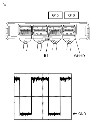
*a Component with harness connected
(EV Control ECU)
Reconnect the E1 electric heater sub-assembly connector.
-
Reconnect the G46 EV control ECU connector.
-
Remove the EV control ECU with the connectors still connected.
-
Measure the waveform of the EV control ECU connector.
OK Waveform is similar to that shown in the illustration. Tech Tips
The waveform varies with the duty ratio.
Item Content Tester Connection G46-18 (WHHD) - G45-6 (E1) Tool Setting 2 V/DIV., 5 ms/DIV. Vehicle Condition
-
Power switch on (Ready)
-
FC coolant temperature less than 50°C (122°F) EV system startup.
-
Blower speed: LO or more
-
Temperature setting: MAX HOT
Result Proceed to OK NG -
NG
REPLACE EV CONTROL ECU Click here
OK
-
-
INSPECT EH FUSE
CAUTION:
Be sure to wear insulated gloves.
-
Turn the power switch off.
-
Remove the service plug grip.
CAUTION:
Do not touch the high-voltage connectors or terminals for 10 minutes after the service plug grip is removed.
Note
After removing the service plug grip, turning the power switch on (READY) may cause a malfunction. Do not turn the power switch on (READY) with the service plug grip removed.
-
Remove the junction block service cover.
Note
Be sure to prevent foreign matter or water from entering the FC inverter input junction assembly.
-
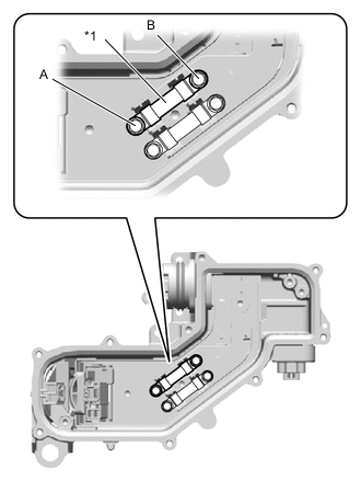
*1 EH Fuse Check that bolts A and B are tightened securely.
-
Measure the resistance according to the value(s) in the table below.
Standard Resistance Tester Item
(Tester Connection)
Condition Specified Condition EH fuse
(A - B)
Always Below 1 Ω Result Proceed to OK NG
NG
REPLACE EH FUSE AND ELECTRIC HEATER SUB-ASSEMBLY EH FUSE: Click here Electric heater sub-assembly: Click here Because the electric heater is the only possible cause of this fuse blowing, replace both the EH fuse and the electric heater sub-assembly at the same time.
OK
-
-
READ VALUE USING GTS (ENGINE COOLANT TEMP)
-
Using the GTS, follow the instructions on the screen to perform the Active Test, and read the Data List values for the water temperature sensor.
-
Operate the integration control and panel assembly so that the following conditions are met.
Item Condition Temperature Setting MAX HOT Blower speed Lo ECO mode switch OFF Water Temperature Below 40°C -
Perform the Active Test according to the display on the GTS.
-
Set the heating three-way valve to the fully closed position.
Body Electrical > Air Conditioner > Active TestTester Display Measurement Item Control Range Diagnostic Note Heater Valve 3 way valve Close, Half, Open -
Body Electrical > Air Conditioner > Active TestTester Display Heater Valve -
-
Read the Data List according to the display on the GTS.
Body Electrical > Air Conditioner > Data ListTester Display Measurement Item Normal Condition Reference Value Diagnostic Note Engine Coolant Temp Heater core inlet water temperature Min.: 1.30°C(34.34°F)
Max.: 90.55°C(194.99°F)
Heater pipe (electric heater sub-assemblyto heater radiator unit sub-assembly) temperature displayed -
Body Electrical > Air Conditioner > Data ListTester Display Engine Coolant Temp
OK The value in the Data List rises Result Proceed to OK NG -
OK
HOW TO TROUBLESHOOT ECU CONTROLLED SYSTEMS Click here
NG
REPLACE ELECTRIC HEATER SUB-ASSEMBLY Click here
-