SIDE AIRBAG SENSOR(for Center Pillar) REMOVAL
CAUTION / NOTICE / HINT
The necessary procedures (adjustment, calibration, initialization, or registration) that must be performed after parts are removed, installed, or replaced during the side airbag sensor assembly removal/installation are shown below.
| Replacement Part or Procedure | Necessary Procedure | Effect/Inoperative when not Performed | Link |
|---|---|---|---|
| Replace side airbag sensor assembly | FC stack assembly on-vehicle inspection* | The FC stack assembly may have been damaged. |
*: Perform an on-vehicle inspection of the FC stack assembly only if the vehicle has been subjected to a strong impact.
Tech Tips
-
Use the same procedure for RHD and LHD vehicles.
-
The procedure listed below is for LHD vehicles.
-
Use the same procedure for the RH and LH sides.
-
The procedure listed below is for the LH side.
PROCEDURE
-
PRECAUTION
Note
After turning the power switch off, waiting time may be required before disconnecting the cable from the negative (-) auxiliary battery terminal. Therefore, make sure to read the disconnecting the cable from the negative (-) auxiliary battery terminal notice before proceeding with work.
-
REMOVE LUGGAGE TRIM SERVICE HOLE COVER
-
DISCONNECT CABLE FROM NEGATIVE AUXILIARY BATTERY TERMINAL
-
Disconnect the cable from the negative (-) auxiliary battery terminal.
CAUTION:
-
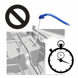
Wait at least 90 seconds after disconnecting the cable from the negative (-) auxiliary battery terminal to disable the SRS system.
-
If the airbag deploys for any reason, it may cause a serious accident.
-
-
-
REMOVE FRONT DOOR SCUFF PLATE
-
DISCONNECT FRONT DOOR OPENING TRIM WEATHERSTRIP
-
REMOVE REAR DOOR SCUFF PLATE
-
DISCONNECT REAR DOOR OPENING TRIM WEATHERSTRIP
-
REMOVE LAP BELT OUTER ANCHOR COVER
-
DISCONNECT FRONT SEAT OUTER BELT ASSEMBLY
-
REMOVE CENTER PILLAR LOWER GARNISH
-
REMOVE SIDE AIRBAG SENSOR ASSEMBLY
-
Check that the power switch is off.
-
Check that the cable is disconnected from the negative (-) auxiliary battery terminal.
CAUTION:
-
Wait at least 90 seconds after disconnecting the cable from negative (-) auxiliary battery terminal to disable the SRS system.
-
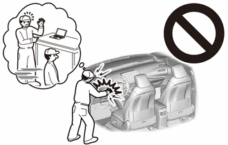
If this procedure is performed without disconnecting the cable from negative (-) auxiliary battery terminal, the airbag may deploy even if an impact is applied only to the No. 2 side airbag sensor assembly. Therefore, make sure that the cable from negative (-) auxiliary battery terminal is connected before performing this procedure.
-
-
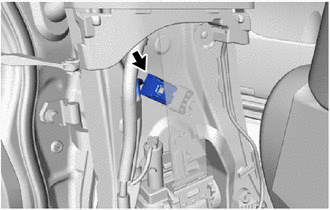
Disconnect the connector.
-
Push down the housing lock and slide the CPA. (At this time, the airbag connector cannot be disconnected yet.)
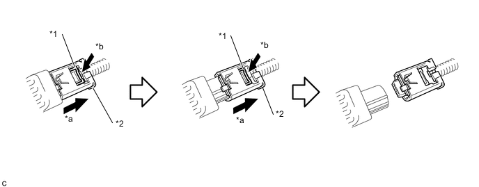
*1 Housing Lock *2 CPA *a Slide *b Push Down Note
-
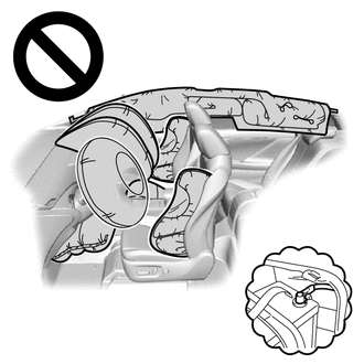
When disconnecting any airbag connector, take care not to damage the airbag wire harness.
-
Do not push down the upper part of the CPA shown in the illustration when disconnecting the airbag connector.
-
-
Push down the housing lock again and disconnect the airbag connector.
-
After disconnecting the connector, check that the position of the housing is correct as shown in the illustration.
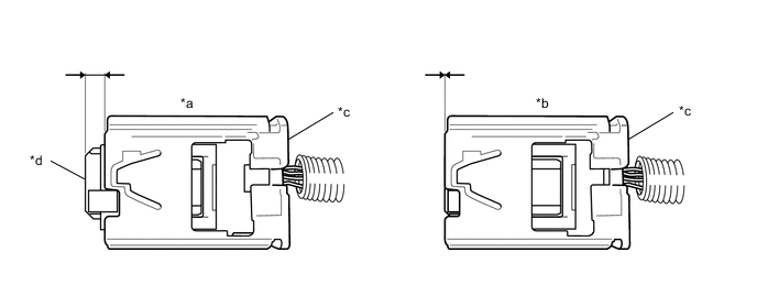
*a Correct *b Incorrect *c CPA *d Housing
-
-
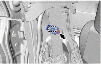
Remove the bolt.
-
Disengage the guide and remove the side airbag sensor assembly.
Note
-
Loosen the bolt while holding the side airbag sensor assembly because the side airbag sensor assembly guide is easily damaged.
-
If the side airbag sensor assembly has been dropped, replace it with a new one.
-
-
-
REMOVE NO. 2 SIDE AIRBAG SENSOR ASSEMBLY
-
Check that the power switch is off.
-
Check that the cable is disconnected from the negative (-) auxiliary battery terminal.
CAUTION:
-
Wait at least 90 seconds after disconnecting the cable from negative (-) auxiliary battery terminal to disable the SRS system.
-
If this procedure is performed without disconnecting the cable from negative (-) auxiliary battery terminal, the airbag may deploy even if an impact is applied only to the No. 2 side airbag sensor assembly. Therefore, make sure that the cable from negative (-) auxiliary battery terminal is connected before performing this procedure.
-
-
Disconnect the connector.
-
Push down the housing lock and slide the CPA. (At this time, the connector cannot be disconnect yet.)
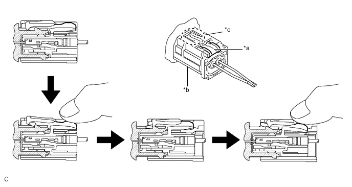
*a Housing Lock *b CPA *c CPA Upper Part - - Note
-
When disconnecting any airbag connector, take care not to damage the airbag wire harness.
-
Do not push down the upper part of the CPA shown in the illustration when disconnecting the airbag connector.
-
-
Push the housing lock again and disconnect the connector.
-
After disconnecting the connector, check that the position of the housing is correct as shown in the illustration.
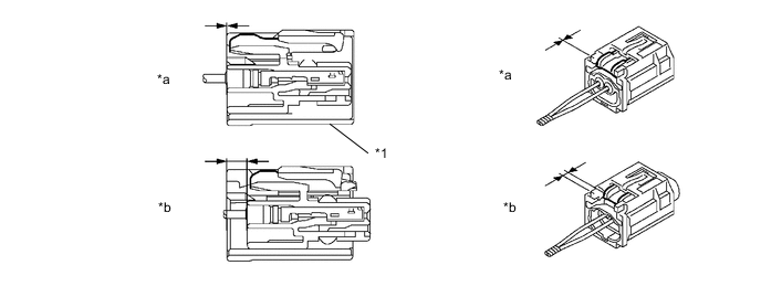
*1 CPA - - *a Incorrect *b Correct
-
-
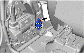
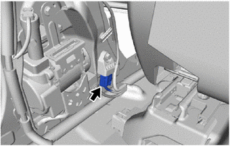
Remove the bolt.
-
Disengage the guide and remove the No. 2 side airbag sensor assembly.
Note
-
Loosen the bolt while holding the No. 2 side airbag sensor assembly because the No. 2 side airbag sensor assembly guide is easily damaged.
-
If the No. 2 side airbag sensor assembly has been dropped, replace it with a new one.
-
-