CENTER AIRBAG SENSOR ASSEMBLY REMOVAL
CAUTION / NOTICE / HINT
The necessary procedures (adjustment, calibration, initialization, or registration) that must be performed after parts are removed, installed, or replaced during the airbag ECU assembly removal/installation are shown below.
| Replacement Part or Procedure | Necessary Procedure | Effects/Inoperative when not Performed | Link |
|---|---|---|---|
| Replace airbag ECU assembly |
|
Brake control / Dynamic control systems | |
| FC stack assembly on-vehicle inspection* | The FC stack assembly may have been damaged. |
*: Perform an on-vehicle inspection of the FC stack assembly only if the vehicle has been subjected to a strong impact.
Tech Tips
-
Use the same procedure for RHD and LHD vehicles.
-
The procedure listed below is for LHD vehicles.
PROCEDURE
-
PRECAUTION
Note
After turning the power switch off, waiting time may be required before disconnecting the cable from the negative (-) auxiliary battery terminal. Therefore, make sure to read the disconnecting the cable from the negative (-) auxiliary battery terminal notice before proceeding with work.
-
REMOVE LUGGAGE TRIM SERVICE HOLE COVER
-
DISCONNECT CABLE FROM NEGATIVE AUXILIARY BATTERY TERMINAL
-
Disconnect the cable from the negative (-) auxiliary battery terminal.
CAUTION:
-
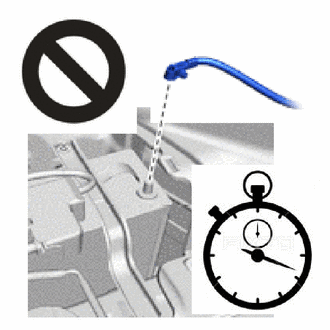
Wait at least 90 seconds after disconnecting the cable from the negative (-) auxiliary battery terminal to disable the SRS system.
-
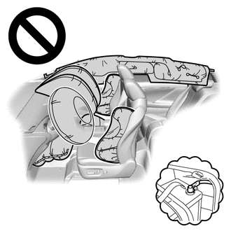
If the airbag deploys for any reason, it may cause a serious accident.
-
-
-
REMOVE COOLER BLOWER ASSEMBLY
-
REMOVE AIRBAG ECU ASSEMBLY
-
Check that the power switch is off.
-
Check that the cable is disconnected from the negative (-) auxiliary battery terminal.
CAUTION:
-
Wait at least 90 seconds after disconnecting the cable from negative (-) auxiliary battery terminal to disable the SRS system.
-
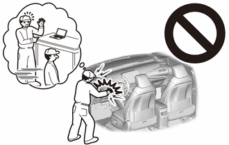
If this procedure is performed without disconnecting the cable from negative (-) auxiliary battery terminal, the airbag may deploy even if an impact is applied only to the airbag ECU assembly. Therefore, make sure that the cable from negative (-) auxiliary battery terminal is disconnected before performing this procedure.
-
-
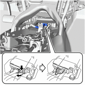
*1 Connector Lock Lever 
Release in this Direction Push and pull the connector lock lever to release the connector lock as shown in the illustration.
-
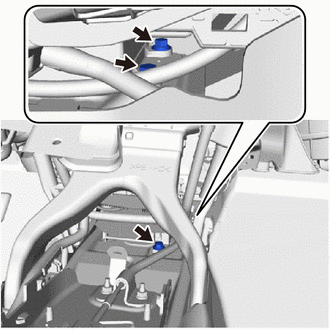
Remove the 3 bolts.
Note
If the airbag ECU assembly has been dropped, or there are any cracks, dents or other defects in the case or connector, replace the airbag ECU assembly with a new one.
-
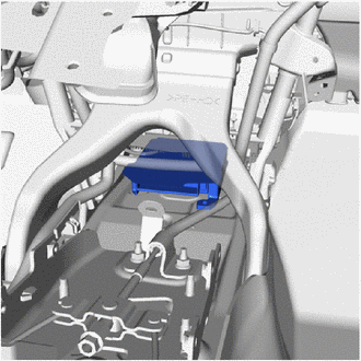
Remove the airbag ECU assembly.
-