SPIRAL CABLE INSTALLATION
CAUTION / NOTICE / HINT
Note
If the vehicle is subjected to a strong impact, the cells inside the FC stack assembly may become misaligned, which could result in a hydrogen leak, so follow the procedures here to perform an on-vehicle inspection of the FC stack assembly.
PROCEDURE
-
PLACE FRONT WHEELS FACING STRAIGHT AHEAD
-
INSPECT SPIRAL CABLE WITH SENSOR SUB-ASSEMBLY
Note
When the following conditions cannot be checked via the check window with the front wheels facing straight ahead, there may be a malfunction in the spiral cable with sensor sub-assembly. In this case, replace the spiral cable with sensor sub-assembly with a new one.
-
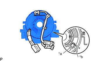
*a Check Window *b U-turn point Check the check window shown in the illustration.
Tech Tips
With the steering wheel straight ahead, align the matchmarks to check the U-turn point of the cable from the check window.
-
If the spiral cable with sensor sub-assembly is not centered, center it.
Note
-
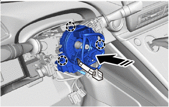
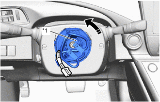
When rotating the spiral cable with sensor sub-assembly, make sure to push on the interlock indicated in the illustration to release the interlock mechanism.
-
Do not turn the spiral with sensor cable sub-assembly using the airbag wire harness.
-
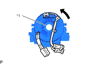
*1 INTERLOCK 
Counterclockwise While pushing on the interlock indicated in the illustration, rotate the spiral cable with sensor sub-assembly counterclockwise slowly by hand until stops.
-
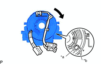
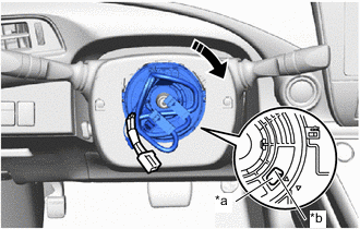
*a Check Window *b U-turn point Clockwise While pushing on the interlock indicated in the illustration, rotate the spiral cable with sensor sub-assembly 2.5 times clockwise from the lock position.
Tech Tips
The spiral cable with sensor sub-assembly will rotate approximately 2.5 times turns to both the left and right from the center.
-
Check the check window shown in the illustration. With the steering wheel straight ahead, align the U-turn point to check from the check window. If the cable cannot be centered, it is possible that the spiral cable with sensor sub-assembly is broken. Replace the spiral cable with sensor sub-assembly with a new one.
-
-
-
INSTALL SPIRAL CABLE WITH SENSOR SUB-ASSEMBLY
Note
-
Do not replace the spiral cable with sensor sub-assembly with the battery connected and the power switch on (IG).
-
Do not rotate the spiral cable with sensor sub-assembly with the battery connected and the power switch on (IG).
-
Check that the power switch is off.
-
Check that the cable is disconnected from the negative (-) auxiliary battery terminal.
CAUTION:
-
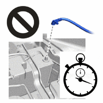
Wait at least 90 seconds after disconnecting the cable from the negative (-) auxiliary battery terminal to disable the SRS system.
-
If the airbag deploys for any reason, it may cause a serious accident.
-
-
Set the turn signal switch to the neutral position.
-

Install in this Direction Engage the claws to install the spiral cable with sensor sub-assembly as shown in the illustration.
-
Connect each connectors.
-
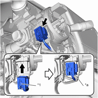
*1 Lock Slider *a Lock Position Connect the airbag connector and check that the slider is in the lock slider.
Tech Tips
If the slider is not in the lock position, the airbag connector is not completely connected. Disconnect the airbag connector, check the airbag connector and Engage the claws to install the spiral cable with sensor sub-assembly as shown in the illustration. terminals and connector housing for deformation or foreign matter, and then reconnect the airbag connector.
-
-
INSTALL UPPER STEERING COLUMN COVER
-
INSTALL METER HOOD SPACER
-
INSTALL LOWER STEERING COLUMN COVER
-
INSPECT AND ADJUST SPIRAL CABLE WITH SENSOR SUB-ASSEMBLY
Note
-
Do not replace the spiral cable with sensor sub-assembly with the battery connected and the power switch on (IG).
-
Do not rotate the spiral cable with sensor sub-assembly with the battery connected and the power switch on (IG).
-
Check that the power switch is off.
-
Check that the cable is disconnected from the negative (-) auxiliary battery terminal.
CAUTION:
Wait at least 90 seconds after disconnecting the cable from the negative (-) auxiliary battery terminal to disable the SRS system. If the airbag deploys for any reason, it may cause a serious accident.
-
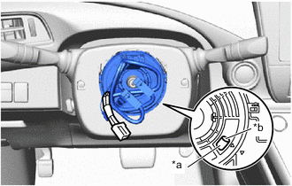
*a Check Window *b U-turn point Check the check window shown in the illustration. With the steering wheel straight ahead, check the U-turn point of the cable from the check window.
Tech Tips
When the spiral cable with sensor sub-assembly is centered, The connector is at the top and the U-turn point can be checked from the check window.
-
If the spiral cable with sensor sub-assembly is not centered, center it.
Note
-
When rotating the spiral cable with sensor sub-assembly, make sure to push on the interlock indicated in the illustration to release the interlock mechanism.
-
Do not turn the spiral cable with sensor sub-assembly using the airbag wire harness.
-
*1 Interlock Counterclockwise While pushing on the interlock indicated in the illustration, rotate the spiral cable with sensor sub-assembly counterclockwise slowly by hand until it stops.
-
*a Check Window *b U-turn point Clockwise While pushing on the interlock indicated in the illustration, rotate the spiral cable with sensor sub-assembly 2.5 times clockwise from the lock position.
Tech Tips
-
The spiral cable with sensor sub-assembly will rotate approximately 2.5 turns to both the left and right from the center.
-
When the spiral cable with sensor sub-assembly is centered, The connector is at the top and the U-turn point can be checked from the check window.
-
If the cable cannot be centered, it is possible that the spiral cable with sensor sub-assembly is broken, Replace the spiral cable with sensor sub-assembly with a new one.
-
-
-
-
INSTALL STEERING WHEEL ASSEMBLY