STEERING PAD REMOVAL

CAUTION / NOTICE / HINT
The necessary procedures (adjustment, calibration, initialization, or registration) that must be performed after parts are removed, installed, or replaced during the horn button assembly removal/installation are shown below.
| Replacement Part or Procedure | Necessary Procedure | Effect/Inoperative when not Performed | Link |
|---|---|---|---|
| Replace horn button assembly | FC stack assembly on-vehicle inspection* | The FC stack assembly may have been damaged. |
*: Perform an on-vehicle inspection of the FC stack assembly only if the vehicle has been subjected to a strong impact.
Note
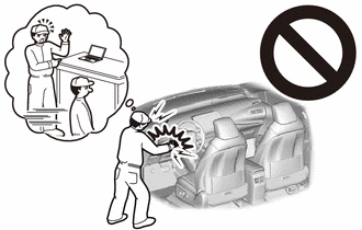
If the vehicle is subjected to a strong impact, the cells inside the FC stack assembly may become misaligned, which could result in a hydrogen leak, so follow the procedures here to perform an on-vehicle inspection of the FC stack assembly.
PROCEDURE
-
PRECAUTION
After turning the power switch off, waiting time may be required before disconnecting the cable from the negative (-) auxiliary battery terminal. Therefore, make sure to read the disconnecting the cable from the negative (-) auxiliary battery terminal notices before proceeding with work.
-
CUSTOMIZE SWITCH
Tech Tips
Because removing the steering column cover is difficult, before disconnecting the negative (-) auxiliary battery terminal, set the steering wheel to the tilt down and telescopic extend positions, and use the custom settings to prohibit the auto away function.
-
REMOVE LUGGAGE TRIM SERVICE HOLE COVER
-
DISCONNECT CABLE FROM NEGATIVE AUXILIARY BATTERY TERMINAL
-
Disconnect the cable from the negative (-) auxiliary battery terminal.
CAUTION:
-
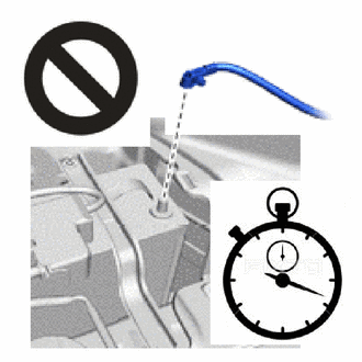
Wait at least 90 seconds after disconnecting the cable from the negative (-) auxiliary battery terminal to disable the SRS system.
-
If the airbag deploys for any reason, it may cause a serious accident.
-
-
-
REMOVE HORN BUTTON ASSEMBLY
CAUTION:
-
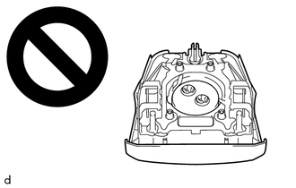
When storing the horn button assembly, keep the airbag deployment side facing upward.
-
If the airbag deploys for any reason, it may cause a serious accident.
-
Check that the power switch is off.
-
Check that the cable is disconnected from the negative (-) auxiliary battery terminal.
CAUTION:
-
Wait at least 90 seconds after disconnecting the cable from the negative (-) auxiliary battery terminal to disable the SRS system.
-
If the airbag deploys for any reason, it may cause a serious accident.
-
-
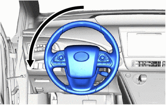
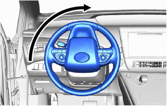
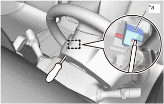
Turn the steering wheel 180° to the left so that the hole in the rear surface of the lower steering wheel cover is on the top side of the upper steering column cover.
-
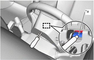
*a Housing Tab Using a T10H "TORX" driver, press in the housing tab, and disengage the metal hook.
Tech Tips
-
Insert the T10H "TORX" driver from the installation holes for the lower steering wheel cover.
-
Insert the T10H "TORX" driver from the upper side of the column cover.
-
For the order of disengaging the hooks, first remove the hook from the hole on the lower side.
-
-
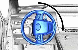
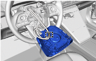
Turn the steering wheel 90° to the right, so that the hole in the rear surface of the lower steering wheel cover is on the top side of the upper steering column cover.
-
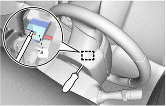
*a Housing Tab Using a T10H "TORX" driver, press in the housing tab, and disengage the metal hook.
CAUTION:
Support the horn button assembly with one hand.
Tech Tips
-
Insert the T10H "TORX" driver from the hole in the rear surface of the steering wheel lower cover.
-
Insert the T10H "TORX" driver from the upper side of the column cover.
-
-
Turn the steering wheel 180° to the right, so that the hole in the rear surface of the lower steering wheel cover is on the top side of the upper steering column cover.
-
*a Housing Tab Using a T10H "TORX" driver, press in the housing tab and disengage the pin.
CAUTION:
Support the horn button assembly with one hand.
Tech Tips
-
Insert the T10H "TORX" driver from the hole in the rear surface of the lower steering wheel cover.
-
Insert the T10H "TORX" driver from the upper side of the column cover.
-
-
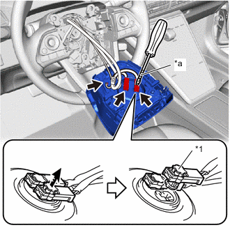
*1 Locking button *a Protective Tape 
Unlock Direction Pull out the horn button assembly from the steering wheel assembly and hold the horn button assembly with one hand.
Note
When separating the horn button assembly, do not pull the airbag wire harness.
-
Disconnect the horn connector from the horn button assembly.
-
Using a screwdriver with its tip wrapped with protective tape, release the 2 locking buttons.
-
Disconnect the 2 airbag connectors to remove the horn button assembly.
-
Disengage the clamp to remove the horn button assembly.
-