AIRBAG SYSTEM, Diagnostic DTC:B1653/35
| DTC Code | DTC Name |
|---|---|
| B1653/35 | Seat Position Airbag Sensor Circuit Malfunction |
DESCRIPTION
The seat position airbag sensor circuit consists of the airbag sensor assembly and seat position airbag sensor.
DTC B1653/35 is stored when a malfunction is detected in the seat position airbag sensor circuit.
| DTC No. | Detection Item | DTC Detection Condition | Trouble Area |
|---|---|---|---|
| B1653/35 | Seat Position Airbag Sensor Circuit Malfunction |
One of the following conditions is met: |
|
-
*1: for LHD
-
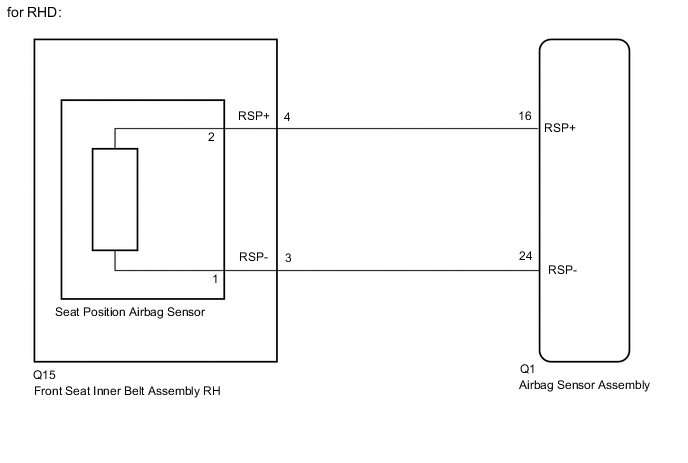
*2: for RHD
WIRING DIAGRAM
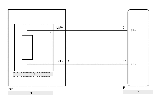
| *a | Seat Position Airbag Sensor |
| *b | Front Seat Inner Belt Assembly LH |
| *c | Airbag Sensor Assembly |
CAUTION / NOTICE / HINT
Note
-
After turning the power switch off, waiting time may be required before disconnecting the cable from the negative (-) auxiliary battery terminal. Therefore, make sure to read the disconnecting the cable from the negative (-) auxiliary battery terminal notices before proceeding with work.
-
When disconnecting the cable from the negative (-) auxiliary battery terminal while performing repairs, some systems need to be initialized after the cable is reconnected.
-
After replacing the airbag sensor assembly, refer to initialization.
PROCEDURE
-
CHECK CONNECTION OF CONNECTORS
-
Turn the power switch off.
-
Disconnect the cable from the negative (-) auxiliary battery terminal, and wait for at least 90 seconds.
-
Check that the connectors are properly connected to the airbag sensor assembly and seat position airbag sensor.
Result Result Proceed to Connectors are properly connected A Connectors are not properly connected B
B 
CONNECT CONNECTORS PROPERLY
A 
-
-
CHECK CONNECTORS
-
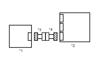
*1 Seat Position Airbag Sensor *2 Airbag Sensor Assembly *3 Front Seat Inner Belt Assembly LH *4 No. 2 Floor Wire Disconnect the connectors from the airbag sensor assembly and seat position airbag sensor.
-
Check that the connectors (on the airbag sensor assembly side and seat position airbag sensor side) are not damaged.
Result Result Proceed to Connectors are not deformed or damaged A Connectors are deformed or damaged B
B
REPLACE NO. 2 FLOOR WIRE OR FRONT SEAT INNER BELT ASSEMBLY LH
A
-
-
CHECK SEAT POSITION AIRBAG SENSOR CIRCUIT
-
Connect the cable to the negative (-) auxiliary battery terminal, and wait for at least 2 seconds.
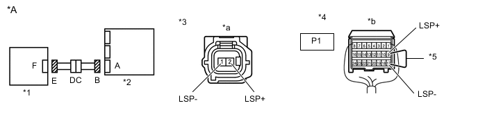
*A for LHD - - *1 Seat Position Airbag Sensor *2 Airbag Sensor Assembly *3 Connector E *4 Connector B *5 Service Wire - - *a Front view of wire harness connector
(to Seat Position Airbag Sensor)
*b Rear view of wire harness connector
(to Airbag Sensor Assembly)
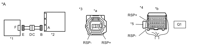
*A for RHD - - *1 Seat Position Airbag Sensor *2 Airbag Sensor Assembly *3 Connector E *4 Connector B *5 Service Wire - - *a Front view of wire harness connector
(to Seat Position Airbag Sensor)
*b Rear view of wire harness connector
(to Airbag Sensor Assembly)
-
Turn the power switch on (IG).
-
Measure the voltage according to the value(s) in the table below.
Standard Voltage for LHD: Tester Connection Switch Condition Specified Condition 1 (LSP-) - Body ground Power switch on (IG) Below 1 V 2 (LSP+) - Body ground Power switch on (IG) Below 1 V for RHD: Tester Connection Switch Condition Specified Condition 1 (RSP-) - Body ground Power switch on (IG) Below 1 V 2 (RSP+) - Body ground Power switch on (IG) Below 1 V -
Turn the power switch off.
-
Disconnect the cable from the negative (-) auxiliary battery terminal, and wait for at least 90 seconds.
-
Using a service wire, connect terminals 9 (LSP+) and 17 (LSP-) of connector B.
Note
Do not forcibly insert the service wire into the terminals of the connector when connecting a service wire.
-
Measure the resistance according to the value(s) in the table below.
Standard Resistance for LHD: Tester Connection Condition Specified Condition 1 (LSP-) - 2 (LSP+) Always Below 1 Ω for RHD: Tester Connection Condition Specified Condition 1 (RSP-) - 2 (RSP+) Always Below 1 Ω -
Disconnect the service wire from connector B.
-
Measure the resistance according to the value(s) in the table below.
Standard Resistance for LHD: Tester Connection Condition Specified Condition 1 (LSP-) - 2 (LSP+) Always 1 MΩ or higher 1 (LSP-) - Body ground Always 1 MΩ or higher 2 (LSP+) - Body ground Always 1 MΩ or higher for RHD: Tester Connection Condition Specified Condition 1 (RSP-) - 2 (RSP+) Always 1 MΩ or higher 1 (RSP-) - Body ground Always 1 MΩ or higher 2 (RSP+) - Body ground Always 1 MΩ or higher Result Proceed to OK NG
NG 
CHECK NO. 2 FLOOR WIRE Click here
OK
-
-
CHECK DTC
-

*1 Seat Position Airbag Sensor *2 Airbag Sensor Assembly Connect the connectors to the airbag sensor assembly and seat position airbag sensor.
-
Connect the cable to the negative (-) auxiliary battery terminal, and wait for at least 2 seconds.
-
Turn the power switch on (IG), and wait for at least 60 seconds.
-
Clear the DTCs.
Body Electrical > SRS Airbag > Clear DTCs -
Turn the power switch off.
-
Turn the power switch on (IG), and wait for at least 60 seconds.
-
Check for DTCs.
Body Electrical > SRS Airbag > Trouble CodesResult Result Proceed to DTC B1653/35 is not output A DTC B1653/35 is output B Tech Tips
Codes other than DTC B1653/35 may be output at this time, but they are not related to this check.
A
USE SIMULATION METHOD TO CHECK Click here
B
-
-
REPLACE SEAT POSITION AIRBAG SENSOR
-
Turn the power switch off.
-
Disconnect the cable from the negative (-) auxiliary battery terminal, and wait for at least 90 seconds.
-
Replace the seat position airbag sensor.
Tech Tips
Perform the inspection using parts from a normal vehicle if possible.
Result Proceed to NEXT
NEXT
-
-
CHECK DTC
-
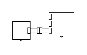
*1 Seat Position Airbag Sensor *2 Airbag Sensor Assembly Connect the cable to the negative (-) auxiliary battery terminal, and wait for at least 2 seconds.
-
Turn the power switch on (IG), and wait for at least 60 seconds.
-
Clear the DTCs.
Body Electrical > SRS Airbag > Clear DTCs -
Turn the power switch off.
-
Turn the power switch on (IG), and wait for at least 60 seconds.
-
Check for DTCs.
Body Electrical > SRS Airbag > Trouble CodesResult Result Proceed to DTC B1653/35 is not output A DTC B1653/35 is output B Tech Tips
Codes other than DTC B1653/35 may be output at this time, but they are not related to this check.
A
END (SEAT POSITION AIRBAG SENSOR WAS DEFECTIVE)
B
REPLACE AIRBAG SENSOR ASSEMBLY Click here
-
-
CHECK NO. 2 FLOOR WIRE
-
Disconnect the No. 2 floor wire connector from the front seat inner belt assembly LH.
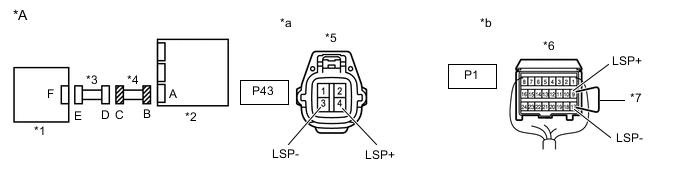
*A for LHD - - *1 Seat Position Airbag Sensor *2 Airbag Sensor Assembly *3 Front Seat Inner Belt Assembly LH *4 No. 2 Floor Wire *5 Connector C *6 Connector B *7 Service Wire - - *a Front view of wire harness connector
(to Front Seat Inner Belt Assembly LH)
*b Rear view of wire harness connector
(to Airbag Sensor Assembly)
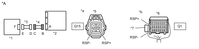
*A for RHD - - *1 Seat Position Airbag Sensor *2 Airbag Sensor Assembly *3 Front Seat Inner Belt Assembly RH *4 No. 2 Floor Wire *5 Connector C *6 Connector B *7 Service Wire - - *a Front view of wire harness connector
(to Front Seat Inner Belt Assembly RH)
*b Rear view of wire harness connector
(to Airbag Sensor Assembly)
-
Connect the cable to the negative (-) auxiliary battery terminal, and wait for at least 2 seconds.
-
Turn the power switch on (IG).
-
Measure the voltage according to the value(s) in the table below.
Standard Voltage for LHD: Tester Connection Switch Condition Specified Condition P43-4 (LSP+) - Body ground Power switch on (IG) Below 1 V P43-3 (LSP-) - Body ground Power switch on (IG) Below 1 V for RHD: Tester Connection Switch Condition Specified Condition Q15-4 (RSP+) - Body ground Power switch on (IG) Below 1 V Q15-3 (RSP-) - Body ground Power switch on (IG) Below 1 V -
Turn the power switch off.
-
Disconnect the cable from the negative (-) auxiliary battery terminal, and wait for at least 90 seconds.
-
Using a service wire, connect terminals 9 (LSP+) and 17 (LSP-) of connector B.
Note
Do not forcibly insert the service wire into the terminals of the connector when connecting a service wire.
-
Measure the resistance according to the value(s) in the table below.
Standard Resistance for LHD: Tester Connection Condition Specified Condition P43-4 (LSP+) - P43-3 (LSP-) Always Below 1 Ω for RHD: Tester Connection Condition Specified Condition Q15-4 (RSP+) - Q15-3 (RSP-) Always Below 1 Ω -
Disconnect the service wire from connector B.
-
Measure the resistance according to the value(s) in the table below.
Standard Resistance for LHD: Tester Connection Condition Specified Condition P43-4 (LSP+) - P43-3 (LSP-) Always 1 MΩ or higher P43-4 (LSP+) - Body ground Always 1 MΩ or higher P43-3 (LSP-) - Body ground Always 1 MΩ or higher for RHD: Tester Connection Condition Specified Condition Q15-4 (RSP+) - Q15-3 (RSP-) Always 1 MΩ or higher Q15-4 (RSP+) - Body ground Always 1 MΩ or higher Q15-3 (RSP-) - Body ground Always 1 MΩ or higher Result Proceed to OK NG
OK
REPLACE FRONT SEAT INNER BELT ASSEMBLY LH Click here
NG
REPLACE NO. 2 FLOOR WIRE
-