AIRBAG SYSTEM, Diagnostic DTC:B1647/82, B1648/82
| DTC Code | DTC Name |
|---|---|
| B1647/82 | Lost Communication with Side Satellite Sensor Bus LH |
| B1648/82 | Side Satellite Sensor Bus LH Initialization Incomplete |
DESCRIPTION
Each of the side airbag sensor assembly LH, rear airbag sensor LH and door side airbag sensor LH is composed of a safing sensor, diagnostic circuit, lateral deceleration sensor, etc. When the airbag sensor assembly receives a signal from the lateral deceleration sensor, the airbag sensor assembly judges whether the SRS should be activated.If a malfunction is detected in the side satellite sensor bus circuit, the airbag sensor assembly stores DTCs B1647/82 and/or B1648/82.
| DTC No. | Detection Item | DTC Detection Condition | Trouble Area | Test Mode / Check Mode |
|---|---|---|---|---|
| B1647/82 | Lost Communication with Side Satellite Sensor Bus LH |
|
|
Does not apply to test/check mode |
| B1648/82 | Side Satellite Sensor Bus LH Initialization Incomplete |
|
|
Does not apply to test/check mode |
WIRING DIAGRAM
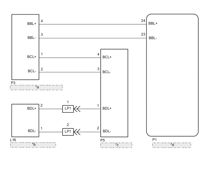
| *a | Side Airbag Sensor Assembly LH |
| *b | Door Side Airbag Sensor LH |
| *c | Rear Side Airbag Sensor LH |
| *d | Airbag Sensor Assembly |
CAUTION / NOTICE / HINT
Note
-
After turning the power switch off, waiting time may be required before disconnecting the cable from the negative (-) auxiliary battery terminal. Therefore, make sure to read the disconnecting the cable from the negative (-) auxiliary battery terminal notices before proceeding with work.
-
When disconnecting the cable from the negative (-) auxiliary battery terminal while performing repairs, some systems need to be initialized after the cable is reconnected.
-
After replacing the airbag sensor assembly, refer to initialization.
Tech Tips
To reproduce the DTC, wiggle each of the SRS airbag system connectors, or drive the vehicle on actual city roads or rough roads.
PROCEDURE
-
CHECK DTC
-
Turn the power switch off.
-
Turn the power switch on (IG), and wait for at least 60 seconds.
-
Clear the DTCs stored in memory.
Body Electrical > SRS Airbag > Clear DTCs -
Turn the power switch off.
-
Turn the power switch on (IG), and wait for at least 60 seconds.
-
Check for DTCs.
Body Electrical > SRS Airbag > Trouble CodesResult Result Proceed to DTC B1647/82 or B1648/82 is output A DTC B1647/82 or B1648/82 is not output B Tech Tips
Codes other than DTC B1647/82 and B1648/82 may be output at this time, but they are not related to this check.
B 
USE SIMULATION METHOD TO CHECK Click here
A 
-
-
CHECK CONNECTION OF CONNECTORS
-
Turn the power switch off.
-
Disconnect the cable from the negative (-) auxiliary battery terminal and wait for at least 90 seconds.
-
Check that the connectors are properly connected to the airbag sensor assembly and side airbag sensor assembly LH.
OK The connectors are properly connected. Result Proceed to OK NG
NG
CONNECT CONNECTORS PROPERLY
OK
-
-
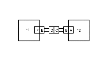
CHECK CONNECTORS
-
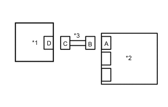
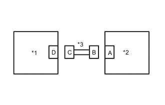
*1 Side Airbag Sensor Assembly LH *2 Airbag Sensor Assembly *3 Floor Wire Disconnect the connectors from the airbag sensor assembly and side airbag sensor assembly LH.
-
Check that the terminals of the connectors are not deformed or damaged.
OK The terminals are not deformed or damaged. Result Proceed to OK NG
NG
REPLACE FLOOR WIRE NO.2
OK
-
-
CHECK SIDE AIRBAG SENSOR ASSEMBLY LH CIRCUIT
-
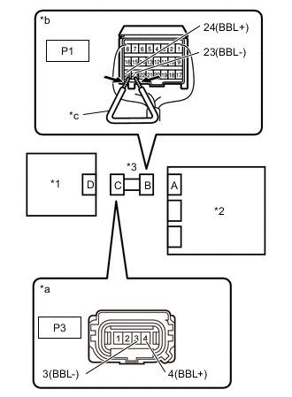
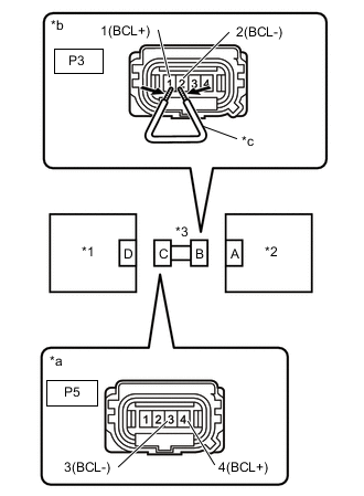
*1 Side Airbag Sensor Assembly LH *2 Airbag Sensor Assembly *3 Floor Wire *a Front view of wire harness connector
(to Side airbag sensor assembly LH)
*b Rear view of wire harness connectorear
(to Airbag Sensor Assembly)
*c Service Wire Disconnect the cable from the negative (-) auxiliary battery terminal and wait for at least 2 seconds.
-
Turn the power switch on (IG).
-
Measure the voltage according to the value(s) in the table below.
Standard Voltage Tester Connection Condition Specified Condition P3-4 (BBL+) - Body ground Power switch on (IG) Below 1 V P3-3 (BBL-) - Body ground Power switch on (IG) Below 1 V -
Turn the power switch off.
-
Disconnect the cable from the negative (-) auxiliary battery terminal and wait for at least 90 seconds.
-
Using a service wire, connect terminals 24 (BBL+) - 23 (BBL-) of connector B.
Note
Do not forcibly insert the service wire into the terminals of the connector when connecting the wire.
-
Measure the resistance according to the value(s) in the table below.
Standard Resistance Tester Connection Condition Specified Condition P3-4 (BBL+) - P3-3 (BBL-) Always Below 1 Ω -
Disconnect the service wire from connector B.
-
Measure the resistance according to the value(s) in the table below.
Standard Resistance Tester Connection Condition Specified Condition P3-4 (BBL+) - P3-3 (BBL-) Always 1 MΩ or higher -
Measure the resistance according to the value(s) in the table below.
Standard Resistance Tester Connection Condition Specified Condition P3-4 (BBL+) - Body ground Always 1 MΩ or higher P3-3 (BBL-) - Body ground Always 1 MΩ or higher Result Proceed to OK NG
NG
REPLACE FLOOR WIRE
OK
-
-
CHECK SIDE AIR BAG SENSOR ASSEMBLY LH
-
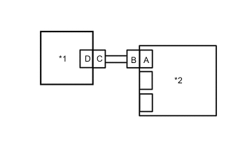
*1 Side Airbag Sensor Assembly RH *2 Airbag Sensor Assembly Connect the connector to airbag sensor assembly.
-
Interchange the side airbag sensor assembly RH with LH and connect the connectors.
-
Disconnect the cable from the negative (-) auxiliary battery terminal and wait for at least 2 seconds.
-
Turn the power switch on (IG), and wait for at least 60 seconds.
-
Clear the DTCs stored in memory.
Body Electrical > SRS Airbag > Clear DTCs -
Turn the power switch off.
-
Turn the power switch on (IG), and wait for at least 60 seconds.
-
Check for DTCs.
Body Electrical > SRS Airbag > Trouble CodesResult Result Proceed to DTC B1642/81 or B1643/81 is output A DTC B1647/82 or B1648/82 is output B DTC B1642/81, B1643/81, B1647/82 and B1648/82 are not output C Tech Tips
Codes other than DTCs B1642/81, B1643/81, B1647/82 and B1648/82 may be output at this time, but they are not related to this check.
-
Turn the power switch off.
-
Disconnect the cable from the negative (-) auxiliary battery terminal and wait for at least 90 seconds.
-
Return the side airbag sensor assembly LH and LH to their original positions and connect the connectors.
A
REPLACE SIDE AIRBAG SENSOR ASSEMBLY LH Click here
C
USE SIMULATION METHOD TO CHECK Click here
B
-
-
CHECK CONNECTION OF CONNECTORS
-
Check that the connectors are properly connected to the rear airbag sensor assembly LH.
OK The connectors are properly connected. Result Proceed to OK NG
NG
CONNECT CONNECTORS PROPERLY
OK
-
-
CHECK CONNECTORS
-
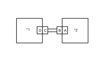
*1 Rear Airbag Sensor LH *2 Side Airbag Sensor Assembly LH *3 Floor Wire Disconnect the connectors from the side airbag sensor assembly LH and rear airbag sensor LH
-
Check that the terminals of the connectors are not deformed or damaged.
OK The terminals are not deformed or damaged. Result Proceed to OK NG
NG
REPLACE FLOOR WIRE
OK
-
-
CHECK REAR AIRBAG SENSOR LH CIRCUIT
-
*1 Rear Airbag Sensor LH *2 Side Airbag Sensor Assembly LH *3 Floor Wire *a Front view of wire harness connector
(to Rear Airbag Sensor LH)
*b Front view of wire harness connectorear
(to Side Airbag Sensor Assembly LH)
*c Service Wire Disconnect the cable from the negative (-) auxiliary battery terminal and wait for at least 2 seconds.
-
Turn the power switch on (IG).
-
Measure the voltage according to the value(s) in the table below.
Standard Voltage Tester Connection Condition Specified Condition P5-4 (BCL+) - Body ground Power switch on (IG) Below 1 V P5-3 (BCL-) - Body ground Power switch on (IG) Below 1 V -
Turn the power switch off.
-
Disconnect the cable from the negative (-) auxiliary battery terminal and wait for at least 90 seconds.
-
Using a service wire, connect terminals 1 (BCL+) - 2 (BCL-) of connector B.
Note
Do not forcibly insert the service wire into the terminals of the connector when connecting the wire.
-
Measure the resistance according to the value(s) in the table below.
Standard Resistance Tester Connection Condition Specified Condition P5-4 (BCL+) - P5-3 (BCL-) Always Below 1 Ω -
Disconnect the service wire from connector B.
-
Measure the resistance according to the value(s) in the table below.
Standard Resistance Tester Connection Condition Specified Condition P5-4 (BCL+) - Body ground Always 1 MΩ or higher -
Measure the resistance according to the value(s) in the table below.
Standard Resistance Tester Connection Condition Specified Condition P5-4 (BCL+) - Body ground Always 1 MΩ or higher P5-3 (BCL-) - Body ground Always 1 MΩ or higher Result Proceed to OK NG
NG
REPLACE FLOOR WIRE
OK
-
-
CHECK REAR AIRBAG SENSOR LH
-
*1 Rear Airbag Sensor LH *2 Side Airbag Sensor Assembly LH Connect the connector to side airbag sensor assembly LH.
-
Interchange the rear airbag sensor RH with LH and connect the connectors.
-
Disconnect the cable from the negative (-) auxiliary battery terminal and wait for at least 2 seconds.
-
Turn the power switch on (IG), and wait for at least 60 seconds.
-
Clear the DTCs stored in memory.
Body Electrical > SRS Airbag > Clear DTCs -
Turn the power switch off.
-
Turn the power switch on (IG), and wait for at least 60 seconds.
-
Check for DTCs.
Body Electrical > SRS Airbag > Trouble CodesResult Result Proceed to DTC B1642/81 or B1643/81 is output A DTC B1647/82 or B1648/82 is output B DTC B1642/81, B1643/81, B1647/82 and B1648/82 are not output C Tech Tips
Codes other than DTCs B1642/81, B1643/81, B1647/82 and B1648/82 may be output at this time, but they are not related to this check.
-
Turn the power switch off.
-
Disconnect the cable from the negative (-) auxiliary battery terminal and wait for at least 90 seconds.
-
Return the rear airbag sensor RH and LH to their original positions and connect the connectors.
A
REPLACE REAR AIRBAG SENSOR LH Click here
C
USE SIMULATION METHOD TO CHECK Click here
B
-
-
CHECK CONNECTION OF CONNECTORS
-
Check that the connectors are properly connected to the door side airbag sensor assembly LH.
OK The connectors are properly connected. Result Proceed to OK NG
NG
CONNECT CONNECTORS PROPERLY
OK
-
-
CHECK CONNECTORS
-
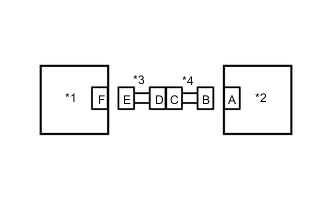
*1 Door Side Airbag Sensor LH *2 Rear Airbag Sensor LH *3 Front Door Wire LH *4 Floor Wire Disconnect the connectors from the rear airbag sensor LH and door side airbag sensor LH.
-
Check that the terminals of the connectors are not deformed or damaged.
OK The terminals are not deformed or damaged. Result Proceed to OK NG
NG
REPLACE FRONT DOOR WIRE LH
OK
-
-
CHECK DOOR SIDE AIRBAG SENSOR LH CIRCUIT
-
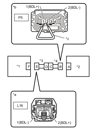
*1 Door Side Airbag Sensor LH *2 Rear Airbag Sensor LH *3 Front Door Wire LH *a Front view of wire harness connector
(to Door Side Airbag Sensor LH)
*b Front view of wire harness connectorear
(to Rear Airbag Sensor LH)
*c Service Wire Disconnect the cable from the negative (-) auxiliary battery terminal and wait for at least 2 seconds.
-
Turn the power switch on (IG).
-
Measure the voltage according to the value(s) in the table below.
Standard Voltage Tester Connection Condition Specified Condition L16-2 (BDL+) - Body ground Power switch on (IG) Below 1 V L16-1 (BDL-) - Body ground Power switch on (IG) Below 1 V -
Turn the power switch off.
-
Disconnect the cable from the negative (-) auxiliary battery terminal and wait for at least 90 seconds.
-
Using a service wire, connect terminals 1 (BDL+) - 2 (BDL-) of connector B.
Note
Do not forcibly insert the service wire into the terminals of the connector when connecting the wire.
-
Measure the resistance according to the value(s) in the table below.
Standard Resistance Tester Connection Condition Specified Condition L16-2 (BDL+) -L16-1 (BDL-) Always Below 1 Ω -
Disconnect the service wire from connector B.
-
Measure the resistance according to the value(s) in the table below.
Standard Resistance Tester Connection Condition Specified Condition L16-2 (BDL+) -L16-1 (BDL-) Always 1 MΩ or higher -
Measure the resistance according to the value(s) in the table below.
Standard Resistance Tester Connection Condition Specified Condition L16-2 (BDL+) - Body ground Always 1 MΩ or higher L16-1 (BDL-) - Body ground Always 1 MΩ or higher Result Proceed to OK NG
NG 
CHECK FLOOR WIRE Click here
OK
-
-
CHECK DOOR SIDE AIR BAG SENSOR LH
-
*1 Door Side Airbag Sensor RH *2 Rear Airbag Sensor LH Connect the connector to rear airbag sensor LH.
-
Interchange the door side airbag sensor RH with LH and connect the connectors.
-
Disconnect the cable from the negative (-) auxiliary battery terminal and wait for at least 2 seconds.
-
Turn the power switch on (IG), and wait for at least 60 seconds.
-
Clear the DTCs stored in memory.
Body Electrical > SRS Airbag > Clear DTCs -
Turn the power switch off.
-
Turn the power switch on (IG), and wait for at least 60 seconds.
-
Check for DTCs.
Body Electrical > SRS Airbag > Trouble CodesResult Result Proceed to DTC B1642/81 or B1643/81 is output A DTC B1647/82 or B1648/82 is output B DTC B1642/81, B1643/81, B1647/82 and B1648/82 are not output C Tech Tips
Codes other than DTCs B1642/81, B1643/81, B1647/82 and B1648/82 may be output at this time, but they are not related to this check.
-
Turn the power switch off.
-
Disconnect the cable from the negative (-) auxiliary battery terminal and wait for at least 90 seconds.
-
Return the door airbag sensor RH and LH to their original positions and connect the connectors.
A
REPLACE DOOR SIDE AIR BAG SENSOR LH Click here
B
REPLACE AIRBAG SENSOR ASSEMBLY Click here
C
USE SIMULATION METHOD TO CHECK Click here
-
-
CHECK FLOOR WIRE
-
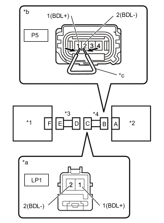
*1 Door Side Airbag Sensor LH *2 Rear Airbag Sensor LH *3 Front Door Wire LH *4 Floor Wire *a Front view of wire harness connector
(to Door Side Airbag Sensor LH)
*b Front view of wire harness connectorear
(to Rear Airbag Sensor LH)
*c Service Wire Disconnect the floor wire connector from the front door wire LH.
-
Disconnect the cable from the negative (-) auxiliary battery terminal and wait for at least 2 seconds.
-
Turn the power switch on (IG).
-
Measure the voltage according to the value(s) in the table below.
Standard Voltage Tester Connection Condition Specified Condition LP1-1 (BDL+) - Body ground Power switch on (IG) Below 1 V LP1-2 (BDL-) - Body ground Power switch on (IG) Below 1 V -
Turn the power switch off.
-
Disconnect the cable from the negative (-) auxiliary battery terminal and wait for at least 90 seconds.
-
Using a service wire, connect terminals 1 (BDL+) - 2 (BDL-) of connector B.
Note
Do not forcibly insert the service wire into the terminals of the connector when connecting the wire.
-
Measure the resistance according to the value(s) in the table below.
Standard Resistance Tester Connection Condition Specified Condition LP1-1 (BDL+) -LP1-2 (BDL-) Always Below 1 Ω -
Disconnect the service wire from connector B.
-
Measure the resistance according to the value(s) in the table below.
Standard Resistance Tester Connection Condition Specified Condition LP1-1 (BDL+) - LP1-2 (BDL-) Always 1 MΩ or higher -
Measure the resistance according to the value(s) in the table below.
Standard Resistance Tester Connection Condition Specified Condition LP1-1 (BDL+) - Body ground Always 1 MΩ or higher LP1-2 (BDL-) - Body ground Always 1 MΩ or higher Result Proceed to OK NG
OK
REPLACE FRONT DOOR WIRE LH
NG
REPLACE FLOOR WIRE
-