REAR DOOR LOCK REMOVAL
CAUTION / NOTICE / HINT
The necessary procedures (adjustment, calibration, initialization, or registration) that must be performed after parts are removed, installed, or replaced during the rear door lock removal/installation are shown below.
| Replacement Part or Procedure | Necessary Procedure | Effects/Inoperative when not Performed | Link |
|---|---|---|---|
|
Initialize Power Window Control System |
|
Tech Tips
-
Use the same procedure for the RHD and LHD vehicles.
-
The procedure listed below is for the LHD vehicles.
-
Use the same procedure for the RH and LH sides.
-
The procedure listed below is for the LH side.
PROCEDURE
-
PRECAUTION
Note
After turning the power switch off, waiting time may be required before disconnecting the cable from the negative (-) auxiliary battery terminal. Therefore, make sure to read the disconnecting the cable from the negative (-) auxiliary battery terminal notices before proceeding with work.
-
REMOVE LUGGAGE TRIM SERVICE HOLE COVER
-
DISCONNECT CABLE FROM NEGATIVE AUXILIARY BATTERY TERMINAL
-
REMOVE REAR DOOR INSIDE HANDLE BEZEL PLUG
-
REMOVE REAR DOOR ARMREST COVER
-
REMOVE NO. 1 REAR DOOR STIFFENER CUSHION
-
REMOVE COURTESY LIGHT ASSEMBLY
-
REMOVE REAR DOOR TRIM BOARD SUB-ASSEMBLY
-
REMOVE REAR DOOR GLASS INNER WEATHERSTRIP
-
REMOVE REAR DOOR SERVICE HOLE COVER
-
REMOVE REAR DOOR GLASS RUN
-
REMOVE REAR DOOR WINDOW REAR LOWER FRAME SUB-ASSEMBLY
-
REMOVE REAR DOOR GLASS SUB-ASSEMBLY
-
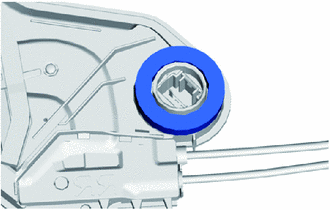
REMOVE REAR DOOR LOCK ASSEMBLY
-
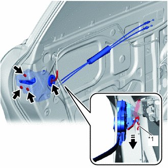
*1 Release plate 
Remove in this Direction Disconnect the connector.
-
Using a T30 "TORX" socket wrench, remove the 3 screws.
-
Disconnect the release plate to remove the rear door lock assembly as shown in the illustration.
-
When reusing the rear door lock assembly:
-
Remove the door lock wiring harness seal from the rear door lock assembly.
-
-
-
REMOVE REAR DOOR LOCK COVER SUB-ASSEMBLY
-
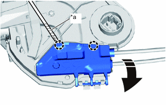
*a Protective Tape Remove in this Direction Using a screwdriver with its tip wrapped in protective tape, disengage the claws as shown in the illustration.
-
Disengage the guides to remove the rear door lock cover sub-assembly from the rear door lock assembly.
-
-
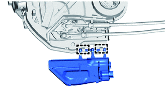
REMOVE REAR DOOR LOCK REMOTE CONTROL CABLE ASSEMBLY
-
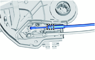
Disengage the guide to remove the rear door lock remote control cable assembly from the rear door lock assembly.
-
-
REMOVE REAR DOOR INSIDE LOCKING CABLE ASSEMBLY
-
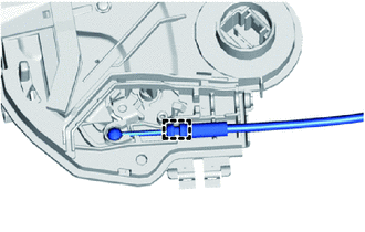
Disengage the guide to remove the rear door inside locking cable assembly from the rear door lock assembly.
-