CAN COMMUNICATION SYSTEM(for LHD) TERMINALS OF ECU
Note
-
After turning the power switch off, waiting time may be required before disconnecting the cable from the negative (-) auxiliary battery terminal. Therefore, make sure to read the disconnecting the cable from the negative (-) auxiliary battery terminal notices before proceeding with work.
-
Turn the power switch off before measuring the resistances between CAN main bus lines and between CAN branch lines.
-
Turn the power switch off before inspecting CAN bus lines for a ground short.
-
Before measuring the resistance of the CAN bus, turn the power switch off and leave the vehicle for 1 minute or more without operating the key or any switches, or opening or closing the doors. After that, disconnect the cable from the negative (-) auxiliary battery terminal and leave the vehicle for 1 minute or more before measuring the resistance.
-
This section describes the standard values for all CAN related components.
Tech Tips
-
Operating the power switch, any other switches or a door triggers related ECU and sensor communication on the CAN. This communication will cause the resistance value to change.
-
Even after DTCs are cleared, if a DTC is stored again after driving the vehicle for a while, the malfunction may be occurring due to vibration of the vehicle. In such a case, wiggling the ECUs or wire harness while performing the inspection below may help determine the cause of the malfunction.
-
NO. 1 CAN JUNCTION CONNECTOR
-
Check the No. 1 CAN junction connector.
-
Connection diagram
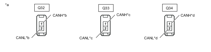
*a Front view of wire harness connector
(to No. 1 CAN Junction Connector)
*b to No. 4 CAN Junction Connector
(for Sub Bus 2)
*c to No. 2 CAN Junction Terminal
(for Sub Bus 2)
*d to Blind Spot Monitor Sensor RH
(for Sub Bus 2)
-
Check the connection diagram of the components which are connected to the No. 1 CAN junction connector.
Terminal No. (Symbol) Wiring Color Connected to Q32-1 (CANH) SB No. 4 CAN junction connector
(for Sub bus 2)
Q32-2 (CANL) W Q33-1 (CANH) G No. 2 CAN junction terminal
(for Sub bus 2)
Q33-2 (CANL) W Q34-1 (CANH) GR Blind spot monitor sensor RH
(for Sub bus 2)
Q34-2 (CANL) W
-
-
-
NO. 2 CAN JUNCTION CONNECTOR
-
Check the No. 2 CAN junction connector.
-
Connection diagram
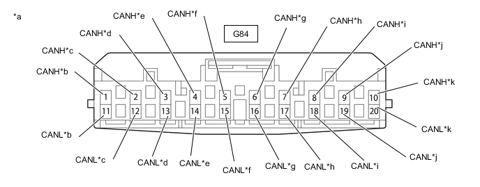
*a Front view of wire harness connector
(to No. 2 CAN Junction Connector)
*b to Skid Control ECU (Brake Booster with Master Cylinder Assembly)
(for V Bus)
*c to FC Control ECU
(for V Bus)
*d to No. 3 CAN Junction Connector
(for V Bus)
*e to Power Steering ECU Assembly
(for V Bus)
*f to Spiral Cable with Sensor Sub-assembly
(for V Bus)
*g to DLC3
(for V Bus)
*h to Airbag ECU Assembly
(for V Bus)
*i to Air Conditioning Amplifier Assembly
(for V Bus)
*j to Main Body ECU (Multiplex Network Body ECU)
(for V Bus)
*k to FC Converter Assembly
(for V Bus)
- - -
Check the connection diagram of the components which are connected to the No. 2 CAN junction connector.
Terminal No. (Symbol) Wiring Color Connected to G84-1 (CANH) B Skid control ECU (brake booster with master cylinder assembly)
(for V Bus)
G84-11 (CANL) W G84-2 (CANH) B FC Control ECU
(for V Bus)
G84-12 (CANL) W G84-3 (CANH) BE No. 3 CAN Junction Connector
(for V Bus)
G84-13 (CANL) W G84-4 (CANH) R Power Steering ECU Assembly
(for V Bus)
G84-14 (CANL) W G84-5 (CANH) V Spiral Cable with Sensor Sub-assembly
(for V Bus)
G84-15 (CANL) W G84-6 (CANH) GR DLC3
(for V Bus)
G84-16 (CANL) W G84-7 (CANH) Y Airbag ECU Assembly
(for V Bus)
G84-17 (CANL) W G84-8 (CANH) LG Air conditioning amplifier assembly
(for V Bus)
G84-18 (CANL) W G84-9 (CANH) BR Main body ECU (multiplex network body ECU)
(for V Bus)
G84-19 (CANL) W G84-10 (CANH) B FC Converter Assembly
(for V Bus)
G84-20 (CANL) W
-
-
-
NO. 3 CAN JUNCTION CONNECTOR
-
Check the No. 3 CAN junction connector.
-
Connection diagram
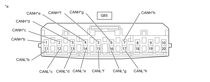
*a Front view of wire harness connector
(to No. 3 CAN Junction Connector)
*b to Combination Meter Assembly
(for V Bus)
*c to Certification ECU (Smart Key ECU Assembly)
(for V Bus)
*d to Radio and Display Receiver Assembly
(for V Bus)
*e to EV Control ECU
(for V Bus)
*f to No. 2 CAN Junction Connector
(for V Bus)
*g to Network Gateway ECU
(for V Bus)
*h to Integration Control and Panel Assembly
(for V Bus)
-
Check the connection diagram of the components which are connected to the No. 3 CAN junction connector.
Terminal No. (Symbol) Wiring Color Connected to G85-1 (CANH) LG Combination Meter Assembly
(for V Bus)
G85-11 (CANL) W G85-2 (CANH) Y Certification ECU (Smart Key ECU Assembly)
(for V Bus)
G85-12 (CANL) W G85-3 (CANH) G Radio and Display Receiver Assembly
(for V Bus)
G85-13 (CANL) W G85-4 (CANH) GR EV Control ECU
(for V Bus)
G85-14 (CANL) W G85-5 (CANH) BE No. 2 CAN Junction Connector
(for V Bus)
G85-15 (CANL) W G85-6 (CANH) L Network Gateway ECU
(for V Bus)
G85-16 (CANL) W G85-7 (CANH) BR Integration Control and Panel Assembly
(for V Bus)
G85-17 (CANL) W
-
-
-
NO. 4 CAN JUNCTION CONNECTOR
-
Check the No. 4 CAN junction connector.
-
Connection diagram
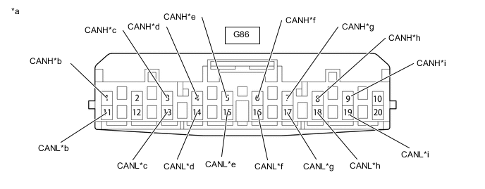
*a Front view of wire harness connector
(to No. 4 CAN Junction Connector)
*b to Skid Control ECU (Brake Booster with Master Cylinder Assembly)
(for Sub Bus 2)
*c to Transmission Control ECU Assembly
(for Sub Bus 2)
*d to No. 1 CAN Junction Connector
(for Sub Bus 2)
*e to Network Gateway ECU
(for Sub Bus 2)
*f to EV Control ECU
(for Sub Bus 2)
*g to Driving Support ECU Assembly
(for Sub Bus 2)
*h to Clearance Warning ECU Assembly
(for Sub Bus 2)
*i to Lane Departure Warning Camera
(for Sub Bus 2)
- - -
Check the connection diagram of the components which are connected to the No. 4 CAN junction connector.
Terminal No. (Symbol) Wiring Color Connected to G86-1 (CANH) B Skid control ECU (brake booster with master cylinder assembly)
(for Sub Bus 2)
G86-11 (CANL) W G86-3 (CANH) B Transmission control ECU assembly
(for Sub Bus 2)
G86-13 (CANL) W G86-4 (CANH) SB No. 1 CAN junction connector
(for Sub Bus 2)
G86-14 (CANL) W G86-5 (CANH) LG Network gateway ECU
(for Sub Bus 2)
G86-15 (CANL) W G86-6 (CANH) P EV control ECU
(for Sub Bus 2)
G86-16 (CANL) W G86-7 (CANH) BR Driving support ECU assembly
(for Sub Bus 2)
G86-17 (CANL) W G86-8 (CANH) B Clearance warning ECU assembly
(for Sub Bus 2)
G86-18 (CANL) W G86-9 (CANH) B Lane departure warning camera
(for Sub Bus 2)
G86-19 (CANL) W
-
-
-
NO. 6 CAN JUNCTION CONNECTOR
-
Check the No. 6 CAN junction connector.
-
Connection diagram
*a Front view of wire harness connector
(to No. 6 CAN Junction Connector)
*b to Main Body ECU (Multiplex Network Body ECU)
(for Sub Bus 1)
*c to No. 7 CAN Junction Connector
(for Sub Bus 1)
*d to Multiplex Tilt and Telescopic ECU
(for Sub Bus 1)
*e to Position Control ECU and Switch Assembly
(for Sub Bus 1)
*f to Outer Mirror Control ECU Assembly LH
(for Sub Bus 1)
*g to Outer Mirror Control ECU Assembly RH
(for Sub Bus 1)
*h to Headlight Light Control ECU Sub-assembly LH
(for Sub Bus 1)
-
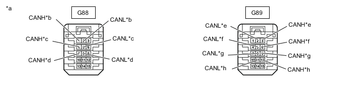
Check the connection diagram of the components which are connected to the No. 6 CAN junction connector.
Terminal No. (Symbol) Wiring Color Connected to G88-1 (CANH) SB Main body ECU (multiplex network body ECU)
(for Sub Bus 1)
G88-2 (CANL) W G88-4 (CANH) L No. 7 CAN junction connector
(for Sub Bus 1)
G88-5 (CANL) W G88-7 (CANH) V Multiplex tilt and telescopic ECU
(for Sub Bus 1)
G88-8 (CANL) W G89-3 (CANH) LG Position control ECU and switch assembly
(for Sub Bus 1)
G89-2 (CANL) W G89-6 (CANH) P Outer mirror control ECU assembly LH
(for Sub Bus 1)
G89-5 (CANL) W G89-9 (CANH) BR Outer mirror control ECU assembly RH
(for Sub Bus 1)
G89-8 (CANL) W G89-12 (CANH) B Headlight light control ECU sub-assembly LH
(for Sub Bus 1)
G89-11 (CANL) W
-
-
-
NO. 7 CAN JUNCTION CONNECTOR
-
Check the No. 7 CAN junction connector.
-
Connection diagram
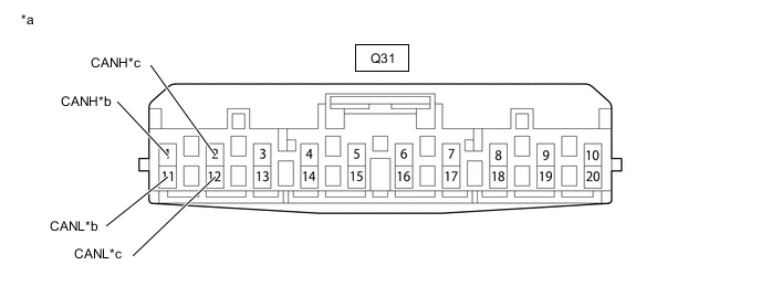
*a Front view of wire harness connector
(to No. 7 CAN Junction Connector)
*b to No. 6 CAN Junction Connector *c to No. 1 CAN Junction Terminal - - -
Check the connection diagram of the components which are connected to the No. 7 CAN junction connector.
Terminal No. (Symbol) Wiring Color Connected to Q31-1 (CANH) L No. 6 CAN junction connector
(for Sub bus 1)
Q31-11 (CANL) W Q31-2 (CANH) G No. 1 CAN junction terminal
(for Sub bus 1)
Q31-12 (CANL) W
-
-
-
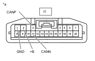
JUNCTION TERMINAL (NO. 1 CAN JUNCTION TERMINAL)
-
Check the junction terminal.
-
Connection diagram

*a Front view of wire harness connector
(to No. 1 CAN Junction Terminal)
*b to No. 7 CAN Junction Connector
(for Sub Bus 1)
-
Check the connection diagram of the components which are connected to the junction terminal.
Terminal No. (Symbol) Wiring Color Connected to Q35-3 (CANP) G No. 7 CAN junction connector
(for Sub bus 1)
Q35-2 (CANN) W
-
-
-
JUNCTION TERMINAL (NO. 2 CAN JUNCTION TERMINAL)
-
Check the junction terminal.
-
Connection diagram

*a Front view of wire harness connector
(to No. 2 CAN Junction Terminal)
*b to No. 1 CAN Junction Connector
(for Sub Bus 2)
-
Check the connection diagram of the components which are connected to the junction terminal.
Terminal No. (Symbol) Wiring Color Connected to Q36-3 (CANH) G No. 1 CAN junction connector
(for Sub bus 2)
Q36-2 (CANL) W
-
-
-
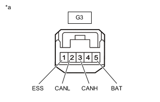
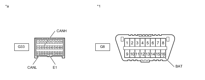
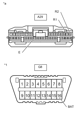
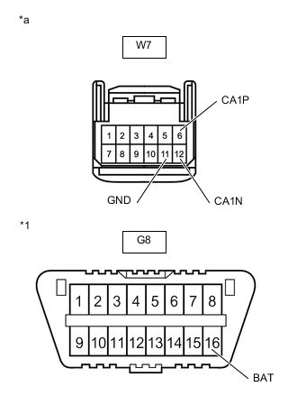
DLC3
-
Disconnect the cable from the negative (-) auxiliary battery terminal.
-
Measure the resistance according to the value(s) in the table below.
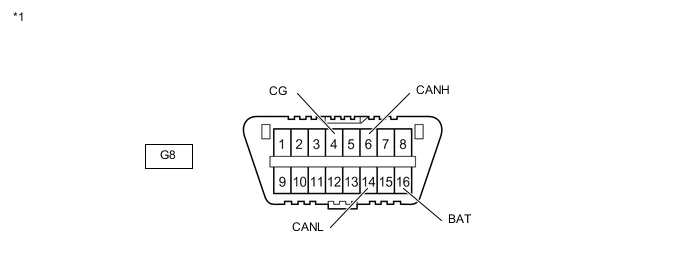
*1 DLC3 - -
-
-
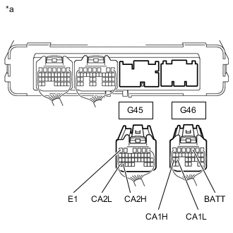
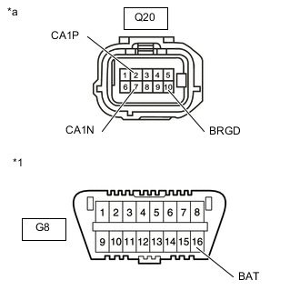
FC CONTROL ECU
-
Disconnect the cable from the negative (-) auxiliary battery terminal.
-
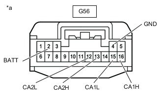
*a Front view of wire harness connector
(to FC Control ECU)
Disconnect the FC control ECU connector.
-
Measure the resistance according to the value(s) in the table below.
-
-
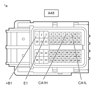
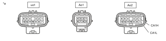
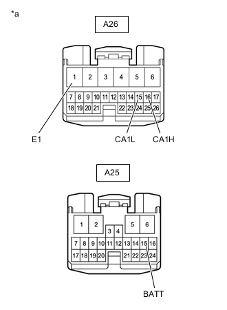
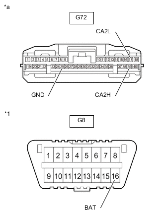
EV CONTROL ECU
-
Disconnect the cable from the negative (-) auxiliary battery terminal.
-
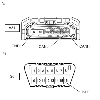
*a Rear view of wire harness connector
(to EV Control ECU)
Disconnect the EV control ECU connectors.
-
Measure the resistance according to the value(s) in the table below.
-
-
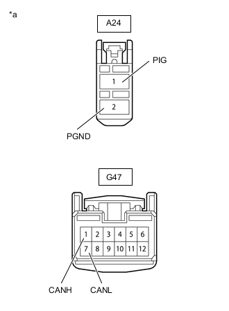
FC CONVERTER ASSEMBLY
*a Component without harness connected
(FC Converter Assembly)
- - CAUTION:
Be sure to wear insulated gloves.
-
Disconnect the cable from the negative (-) auxiliary battery terminal.
-
Check that the service plug grip is not installed to FC stack assembly and EV battery.
Note
After removing the service plug grip, do not turn the power switch on (READY), unless instructed by the repair manual because this may cause a malfunction.
-
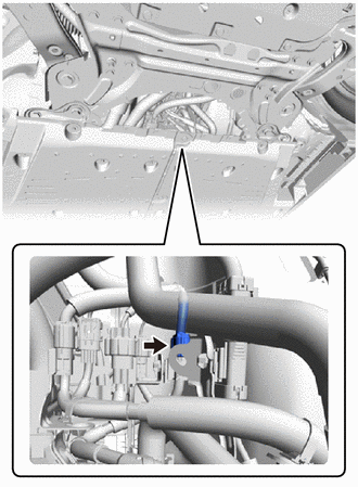
Disconnect the FC converter assembly connector.
-
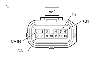
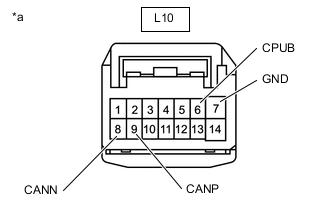
*a Front view of wire harness connector
(to FC Converter Assembly)
Measure the resistance according to the value(s) in the table below.
-
-
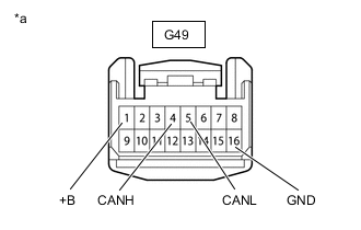
COMBINATION METER ASSEMBLY
-
Disconnect the cable from the negative (-) auxiliary battery terminal.
-
*a Front view of wire harness connector
(to Combination Meter Assembly)
Disconnect the combination meter assembly connector.
-
Measure the resistance according to the value(s) in the table below.
-
-
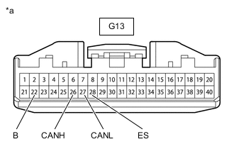
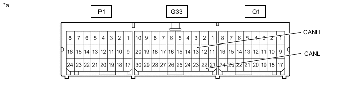
INSTRUMENT PANEL JUNCTION BLOCK ASSEMBLY AND MAIN BODY ECU (MULTIPLEX NETWORK BODY ECU)
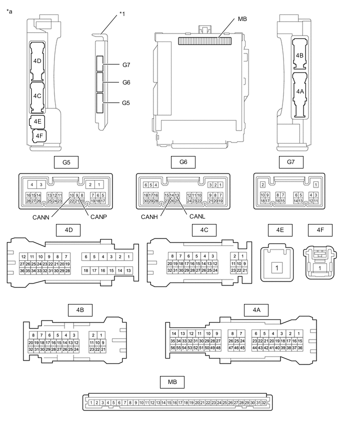
*1 Main Body ECU (Multiplex Network Body ECU) - - *a Component without harness connected
(Instrument Panel Junction Block Assembly and Main Body ECU (Multiplex Network Body ECU))
- -
-
Disconnect the cable from the negative (-) auxiliary battery terminal.
-
Disconnect the main body ECU (multiplex network body ECU) connectors.
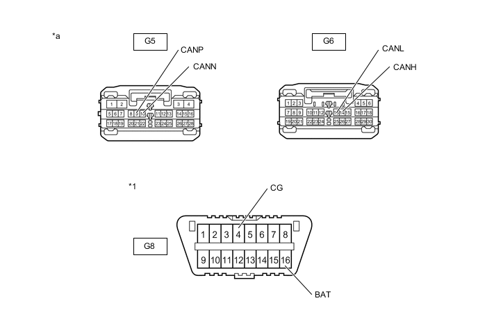
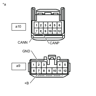
*1 DLC3 - - *a Front view of wire harness connector
(to Main Body ECU (Multiplex Network Body ECU))
- - -
Measure the resistance according to the value(s) in the table below.
-
-
SKID CONTROL ECU (BRAKE BOOSTER WITH MASTER CYLINDER ASSEMBLY)
-
Disconnect the cable from the negative (-) auxiliary battery terminal.
-
*a Front view of wire harness connector
(to Skid Control ECU (Brake Booster with Master Cylinder Assembly))
Disconnect the skid control ECU (brake booster with master cylinder assembly) connector.
-
Measure the resistance according to the value(s) in the table below.
-
-
SPIRAL CABLE WITH SENSOR SUB-ASSEMBLY
-
Disconnect the cable from the negative (-) auxiliary battery terminal.
-
*a Front view of wire harness connector
(to Spiral Cable with Sensor Sub-assembly)
Disconnect the spiral cable with sensor sub-assembly connector.
-
Measure the resistance according to the value(s) in the table below.
-
-
TRANSMISSION CONTROL ECU ASSEMBLY
-
Disconnect the cable from the negative (-) auxiliary battery terminal.
-
*a Front view of wire harness connector
(to Transmission Control ECU Assembly)
Disconnect the transmission control ECU assembly connectors.
-
Measure the resistance according to the value(s) in the table below.
-
-
POWER STEERING ECU ASSEMBLY
-
Disconnect the cable from the negative (-) auxiliary battery terminal.
-
*a Front view of wire harness connector
(to Power Steering ECU Assembly)
Disconnect the power steering ECU assembly connectors.
-
Measure the resistance according to the value(s) in the table below.
-
-
AIRBAG ECU ASSEMBLY
*a Component without harness connected
(Airbag ECU Assembly)
- -
-
Disconnect the cable from the negative (-) auxiliary battery terminal.
-
Disconnect the airbag ECU assembly connector.
*1 DLC3 - - *a Front view of wire harness connector
(to Airbag ECU Assembly)
- - -
Measure the resistance according to the value(s) in the table below.
-
-
CERTIFICATION ECU (SMART KEY ECU ASSEMBLY)
-
Disconnect the cable from the negative (-) auxiliary battery terminal.
-
*a Front view of wire harness connector
(to Certification ECU (Smart Key ECU Assembly))
Disconnect the certification ECU (smart key ECU assembly) connector.
-
Measure the resistance according to the value(s) in the table below.
-
-
RADIO AND DISPLAY RECEIVER ASSEMBLY
-
Disconnect the cable from the negative (-) auxiliary battery terminal.
-
*a Front view of wire harness connector
(to Radio and Display Receiver Assembly)
Disconnect the radio and display receiver assembly connector.
-
Measure the resistance according to the value(s) in the table below.
-
-
AIR CONDITIONING AMPLIFIER ASSEMBLY
-
Disconnect the cable from the negative (-) auxiliary battery terminal.
-
*a Front view of wire harness connector
(to Air Conditioning Amplifier Assembly)
Disconnect the air conditioning amplifier assembly connector.
-
Measure the resistance according to the value(s) in the table below.
-
-
NETWORK GATEWAY ECU
-
Disconnect the cable from the negative (-) auxiliary battery terminal.
-
*a Front view of wire harness connector
(to Network Gateway ECU)
Disconnect the network gateway ECU connector.
-
Measure the resistance according to the value(s) in the table below.
-
-
HEADLIGHT LIGHT CONTROL ECU SUB-ASSEMBLY LH
-
Disconnect the cable from the negative (-) auxiliary battery terminal.
-
*1 DLC3 *a Front view of wire harness connector
(to Headlight Light Control ECU Sub-assembly LH)
Disconnect the headlight light control ECU sub-assembly LH connector.
-
Measure the resistance according to the value(s) in the table below.
-
-
OUTER MIRROR CONTROL ECU ASSEMBLY LH
-
Disconnect the cable from the negative (-) auxiliary battery terminal.
-
*a Front view of wire harness connector
(to Outer Mirror Control ECU Assembly LH)
Disconnect the outer mirror control ECU assembly LH connector.
-
Measure the resistance according to the value(s) in the table below.
-
-
OUTER MIRROR CONTROL ECU ASSEMBLY RH
-
Disconnect the cable from the negative (-) auxiliary battery terminal.
-

*a Front view of wire harness connector
(to Outer Mirror Control ECU Assembly RH)
Disconnect the outer mirror control ECU assembly RH connector.
-
Measure the resistance according to the value(s) in the table below.
-
-
POSITION CONTROL ECU AND SWITCH ASSEMBLY
-
Disconnect the cable from the negative (-) auxiliary battery terminal.
-
*a Front view of wire harness connector
(to Position Control ECU and Switch Assembly)
Disconnect the position control ECU and switch assembly connectors.
-
Measure the resistance according to the value(s) in the table below.
-
-
MULTIPLEX TILT AND TELESCOPIC ECU
-
Disconnect the cable from the negative (-) auxiliary battery terminal.
-
*a Front view of wire harness connector
(to Multiplex Tilt and Telescopic ECU)
Disconnect the multiplex tilt and telescopic ECU connector.
-
Measure the resistance according to the value(s) in the table below.
-
-
BLIND SPOT MONITOR SENSOR RH
-
Disconnect the cable from the negative (-) auxiliary battery terminal.
-
*1 DLC3 *a Front view of wire harness connector
(to Blind Spot Monitor Sensor RH)
Disconnect the blind spot monitor sensor RH connector.
-
Measure the resistance according to the value(s) in the table below.
-
-
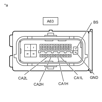
DRIVING SUPPORT ECU ASSEMBLY
-
Disconnect the cable from the negative (-) auxiliary battery terminal.
-
*1 DLC3 *a Front view of wire harness connector
(to Driving Support ECU Assembly)
Disconnect the driving support ECU assembly connector.
-
Measure the resistance according to the value(s) in the table below.
-
-
INTEGRATION CONTROL AND PANEL ASSEMBLY
-
Disconnect the cable from the negative (-) auxiliary battery terminal.
-
*a Front view of wire harness connector
(to Integration Control and Panel Assembly)
Disconnect the integration control and panel assembly connector.
-
Measure the resistance according to the value(s) in the table below.
-
-
CLEARANCE WARNING ECU ASSEMBLY
-
Disconnect the cable from the negative (-) auxiliary battery terminal.
-
*1 DLC3 *a Front view of wire harness connector
(to Clearance Warning ECU Assembly)
Disconnect the clearance warning ECU assembly connector.
-
Measure the resistance according to the value(s) in the table below.
-
-
LANE DEPARTURE WARNING CAMERA
-
Disconnect the cable from the negative (-) auxiliary battery terminal.
-
*1 DLC3 *a Front view of wire harness connector
(to Lane Departure Warning Camera)
Disconnect the lane departure warning camera connector.
-
Measure the resistance according to the value(s) in the table below.
-
-
DIAGNOSIS RECORDER ECU (w/ Diagnosis Recorder ECU)
-
Disconnect the cable from the negative (-) auxiliary battery terminal.
-
*a Front view of wire harness connector
(to Diagnosis Recorder ECU)
Disconnect the diagnosis recorder ECU connector.
-
Measure the resistance according to the value(s) in the table below.
-