CHARGING SYSTEM ON-VEHICLE INSPECTION
CAUTION / NOTICE / HINT
CAUTION:
-
This vehicle has contains high voltage circuits standardized with orange colored wiring and connectors, so follow the instructions in this manual to perform the procedures correctly.
-
If the correct procedures are not followed according to the instructions in this manual, there is a danger of electric shock from the high voltage circuits.
-

Be sure to wear insulating gloves when working on high voltage wiring or components.
-
If work is performed without wearing insulating gloves, there is a danger of electric shock.
PROCEDURE
-
PRECAUTION
Note
After turning the power switch off, waiting time may be required before disconnecting the cable from the negative (-) auxiliary battery terminal. Therefore, make sure to read the disconnecting the cable from the negative (-) auxiliary battery terminal notices before proceeding with work.
-
CHECK AUXILIARY BATTERY
-
Check that the auxiliary battery cables are connected to the correct terminals.
If they are not, connect them properly.
-
Check the auxiliary battery for damage and deformation.
If severe damage, deformation or leakage is found, replace the auxiliary battery.
-
-
CHECK AUXILIARY BATTERY VOLTAGE
-
Turn the power switch off and turn on the high beam headlights for 30 seconds.
-
Turn off the headlight switch.
-
Measure the auxiliary battery voltage according to the value(s) in the table below.
Result Tester Connection Condition Specified Condition Result Positive (+) auxiliary battery terminal - Negative (-) auxiliary battery terminal 20°C (68°F), power switch off 12.0 V or higher Auxiliary battery is OK Below 12.0 V Recharge auxiliary battery
-
-
RECHARGE AUXILIARY BATTERY
-
Recharge the auxiliary battery.
Tech Tips
-
Recharge the auxiliary battery according to the charger's instructions.
-
Apply the appropriate charging current according to the type of auxiliary battery shown in the table below.
Auxiliary Battery Type Charging Current S46B24R 5 A or less
-
-
Turn the power switch off and turn on the high beam headlights for 30 seconds.
-
Turn off the headlight switch.
-
Measure the auxiliary battery voltage according to the value(s) in the table below.
Result Tester Connection Condition Specified Condition Result Cable from positive (+) auxiliary battery terminal - Cable from negative (-) auxiliary battery terminal 20°C (68°F), power switch off 12.0 V or higher Auxiliary battery is OK Below 12.0 V Recharge auxiliary battery
-
-
CHECK AUXILIARY BATTERY TERMINAL, FUSIBLE LINK AND FUSE
-
Check that the auxiliary battery terminals are not loose or corroded.
- Torque:
- Positive (+) auxiliary battery terminal
- 5.4 N*m { 55 kgf*cm, 48 in.*lbf }
- Negative (-) auxiliary battery terminal
- 5.4 N*m { 55 kgf*cm, 48 in.*lbf }
-
Measure the resistance of each fusible link and fuse for the auxiliary battery charging system.
-
-
CHECK AMD TERMINAL
CAUTION:
Wear insulated gloves.
-
Remove the service plug grip (EV).
-
Remove the FC stack service plug grip.
-
Check that the AMD terminal is connected securely, and there is no contact problem.
If there are any arc marks, replace the affected parts.
-
Check that the nut for the AMD terminal is tightened to the specified torque.
If there are no arc marks and the AMD terminal connection is faulty, connect the AMD terminal securely.
-
Install the FC stack service plug grip.
-
Install the service plug grip (EV).
-
-
DC/DC CONVERTER FUNCTION
-
Connect the AC/DC 400 A probe to the positive (+) auxiliary battery cable.
-
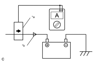
*a AC/DC 400 A probe *b Current Flowing into Auxiliary Battery 
Probe Direction Turn the power switch on (READY) and leave the vehicle as it is until the electric current flowing into the auxiliary battery becomes 10 A or less.
-
Turn the power switch on (READY) with the headlight position switch and blower motor switch in the HI position, and the rear window defogger turned on.
-
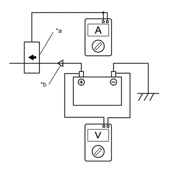
*a AC/DC 400 A probe *b Current Flowing from Auxiliary Battery Probe Direction Measure the current and voltage according to the value(s) in the table below.
Result Item Tester Connection Condition Specified Condition Current flowing from auxiliary battery Positive (+) auxiliary battery cable Power switch on (READY)(The high beam headlights are on, the blower motor switch is in the HI position, and the rear window defogger is turned on.) 0 A or less(No current from auxiliary battery) Auxiliary battery voltage Positive (+) auxiliary battery terminal - Negative (-) auxiliary battery terminal 13.8 to 14.7 V If the result is not as specified, replace the inverter with converter assembly.
-