RADIO RECEIVER REMOVAL
CAUTION / NOTICE / HINT
Tech Tips
-
Use the same procedure for RHD and LHD vehicle.
-
The procedure listed below is for LHD vehicles.
PROCEDURE
-
PRECAUTION
Note
After turning the power switch off, waiting time may be required before disconnecting the cable from the negative (-) auxiliary battery terminal. Therefore, make sure to read the disconnecting the cable from the negative (-) auxiliary battery terminal notices before proceeding with work.
-
REMOVE LUGGAGE TRIM SERVICE HOLE COVER
-
DISCONNECT CABLE FROM NEGATIVE AUXILIARY BATTERY TERMINAL
-
DISCONNECT INTEGRATION CONTROL AND PANEL ASSEMBLY
-
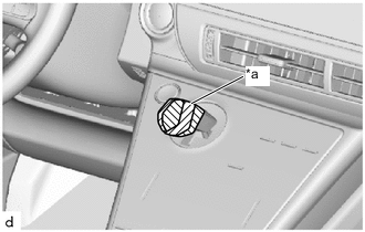
*a Protective Tape Install the protective tape.
-
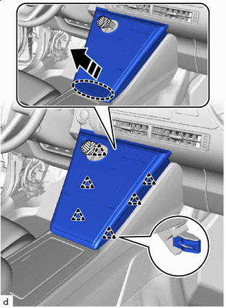

Place Hands Here 
Remove in this Direction Pull in the direction shown by the arrows in the illustration to disengage the clips and raise up the integration control and panel assembly.
Note
To avoid damaging the integration control and panel assembly or breaking the clips, do not lift up the integration control and panel assembly too much.
-
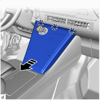
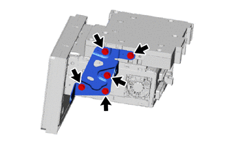
Remove in this Direction Pull in the direction shown by the arrows in the illustration, disengage the claws, and disconnect the integration control and panel assembly.
-
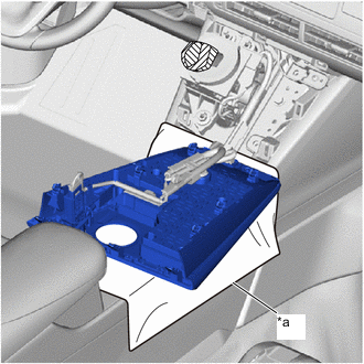
*a Cloth Put the cloth over the front console box, and place the integration control and panel asembly on it.
-
-
REMOVE INSTRUMENT PANEL CENTER REGISTER ASSEMBLY
-
REMOVE RADIO RECEIVER ASSEMBLY
-
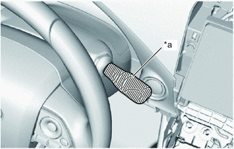
*a Protective Tape Wrap the windshield wiper switch assembly in protective tape.
-
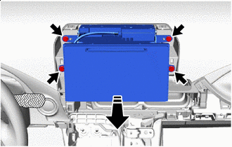
Remove in this Direction Remove the 4 bolts.
-
Pull in the direction shown by the arrow in the illustration, and pull out the radio receiver assembly.
-
Disconnect the connectors to remove the radio receiver assembly.
-
-
REMOVE NAVIGATION WIRE
-
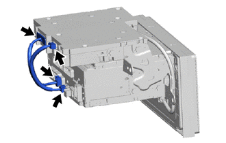
Disconnect the 4 connectors to remove the navigation wire.
-
-
REMOVE NO. 2 RADIO RECEIVER BRACKET
-
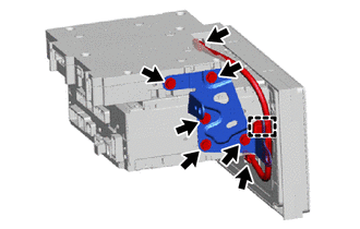
Disconnect the 2 connectors.
-
Remove the 5 bolts and the No. 2 radio receiver bracket.
-
Disengage the clamp to remove the telephone antenna cord sub-assembly.
-
-
REMOVE NO. 1 RADIO RECEIVER BRACKET
-
Remove the 5 bolts and the No. 1 radio receiver bracket.
-
-
REMOVE NAVIGATION COMPUTER ASSEMBLY
-
Remove the navigation computer assembly.
-