BRAKE BOOSTER PUMP(for RHD) INSTALLATION
PROCEDURE
-
INSTALL BRAKE BOOSTER PUMP ASSEMBLY
-
Install the 2 brake actuator bracket cushions to the brake actuator bracket assembly.
-
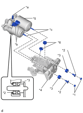
*1 Nut *2 Brake Actuator Case Collar *3 Brake Booster Pump Bushing *4 Brake Actuator Bracket Assembly *5 Brake Booster Pump Assembly *6 Brake Actuator Bracket Cushion *a Union *b Connector *c Stud Install the brake booster pump assembly, 2 brake booster pump bushings and 2 brake actuator case collars to the brake actuator bracket assembly with the 2 nuts.
- Torque:
- 5.4 N*m { 55 kgf*cm, 48 in.*lbf }
Note
-
When handling the brake booster pump assembly, do not hold it at the parts marked *a, *b and *c in the illustration.
-
Do not drop the brake booster pump assembly when carrying it. Do not use a brake booster pump assembly that has been dropped.
-
Do not allow brake fluid to contact the inside of the connector.
-
When installing the brake booster pump assembly to the brake actuator bracket assembly, confirm that the 2 brake actuator bracket cushions are on the brake actuator bracket assembly, and brake booster pump bushing and brake booster pump collar are on the brake booster pump assembly.
-
Do not remove the hole plug before installing a new brake booster pump assembly because the brake booster pump assembly is filled with brake fluid.
-
-
INSTALL NO.1 BRAKE TUBE CLAMP BRACKET
-
Install the No. 1 brake tube clamp bracket to the brake booster pump with bracket assembly with the bolt.
- Torque:
- 7.0 N*m { 71 kgf*cm, 62 in.*lbf }
-
-
INSTALL BRAKE BOOSTER PUMP WITH BRACKET ASSEMBLY
-
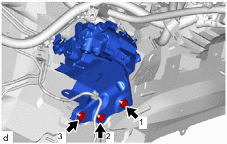
Install the brake booster pump with bracket assembly with the 3 nuts.
- Torque:
- 19 N*m { 194 kgf*cm, 14 ft.*lbf }
Note
Tighten the 3 nuts in the order shown in the illustration.
-
Install the wire harness clamp bracket to the brake booster pump with bracket assembly with the bolt.
- Torque:
- 8.4 N*m { 86 kgf*cm, 74 in.*lbf }
-
Engage the clamp to install the wire harness to the brake booster pump assembly with bracket.
-
Engage the clamp to install the front No. 4 brake tube to the brake booster pump with bracket assembly.
-
Connect the 2 brake booster pump assembly connectors.
-
Engage the clamp to install the wire harness to the brake booster pump with bracket assembly.
-
-
INSTALL FRONT SUSPENSION CROSSMEMBER SUB-ASSEMBLY
-
CONNECT FRONT NO. 1 BRAKE TUBE
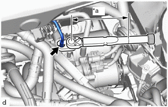
*a Torque Wrench Fulcrum Length
-
Using a 10 mm union nut wrench, connect the front No. 1 brake tube to the brake booster pump with bracket assembly.
- Torque:
- Specified tightening torque
- 15.2 N*m { 155 kgf*cm, 11 ft.*lbf }
Tech Tips
-
Calculate the torque wrench reading when changing the fulcrum length of the torque wrench.
-
When using a union nut wrench (fulcrum length of 22 mm (0.866 in.)) + torque wrench (fulcrum length of 162 mm (6.37 in.)): 13.4 N*m (137 kgf*cm, 10 ft.*lbf)
-
-
INSTALL NO. 6 BRAKE TUBE CLAMP
-
Install the No. 6 brake tube clamp with the bolt.
- Torque:
- 7.0 N*m { 71 kgf*cm, 62 in.*lbf }
-
-
CONNECT BRAKE ACTUATOR HOSE
-
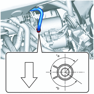
*a 135° *b 145° 
Front of the Vehicle Connect the brake actuator hose to the brake booster pump with bracket assembly , and slide the clip to secure it
Note
-
Make sure to match the identification mark on the hose with the brake booster pump with bracket assembly rib.
-
Install the clip within the range shown in the illustration.
-
-
-
INSTALL WIRING HARNESS CLAMP BRACKET
-
Install the wire harness clamp bracket to the brake booster pump with bracket assembly with the bolt and nut.
- Torque:
- 8.4 N*m { 86 kgf*cm, 74 in.*lbf }
-
-
CONNECT BRAKE MASTER CYLINDER RESERVOIR WITH BRACKET
-
BLEED NO. 1 BRAKE ACTUATOR TUBE
-
INSTALL BRAKE MASTER CYLINDER RESERVOIR WITH BRACKET
-
FILL RESERVOIR WITH BRAKE FLUID
-
CONNECT CABLE TO NEGATIVE AUXILIARY BATTERY TERMINAL
-
INSTALL LUGGAGE TRIM SERVICE HOLE COVER
-
BLEED BRAKE SYSTEM
-
INSPECT BRAKE FLUID LEAK
-
INSTALL OUTER COWL TOP PANEL SUB-ASSEMBLY
-
INSTALL COWL BODY MOUNTING REINFORCEMENT RH
-
INSTALL NO. 1 HEATER AIR DUCT SPLASH SHIELD SEAL
-
INSTALL WATER GUARD PLATE RH
-
INSTALL WINDSHIELD WIPER MOTOR AND LINK
-
CLEAR DTC