BRAKE BOOSTER PUMP(for LHD) REMOVAL
CAUTION / NOTICE / HINT
The necessary procedures (adjustment, calibration, initialization, or registration) that must be performed after parts are removed, installed, or replaced during the brake booster pump assembly removal/installation are shown below.
CAUTION / NOTICE / HINT
| Replacement Part or Procedure | Necessary Procedure | Effects/Inoperative when not Performed | Link |
|---|---|---|---|
| Replacement of brake booster pump assembly |
|
|
|
| Front wheel alignment adjustment |
|
VSC malfunctioning | |
| Adjust lane departure warning camera | Lane departure alert system |
Note
While the auxiliary battery is connected, even if the power switch is off, the brake control system activates when the brake pedal is depressed or any door courtesy switch is turned on. Therefore, when servicing brake system components, do not depress the brake pedal or open/close the doors while the auxiliary battery is connected.
PROCEDURE
-
PRECAUTION
Note
After turning the power switch off, waiting time may be required before disconnecting the cable from the negative (-) auxiliary battery terminal. Therefore, make sure to read the disconnecting the cable from the negative (-) auxiliary battery terminal notices before proceeding with work.
-
REMOVE BRAKE BOOSTER WITH MASTER CYLINDER ASSEMBLY
-
REMOVE WIRING HARNESS CLAMP BRACKET
-
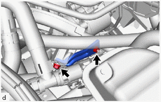
Remove the bolt, nut and wire harness clamp bracket from the brake booster pump with bracket assembly.
-
-
DISCONNECT BRAKE ACTUATOR HOSE
-
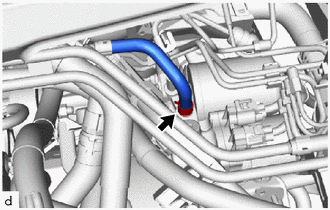
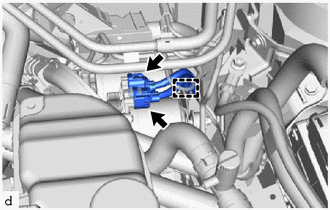
Slide the clip and disconnect the brake actuator hose from the brake booster pump with bracket assembly.
-
-
REMOVE NO. 6 BRAKE TUBE CLAMP
-
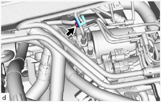
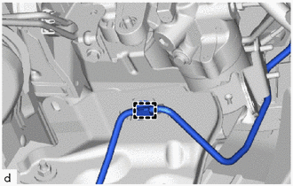
Remove the bolt and No. 6 brake tube clamp from the brake booster pump with bracket assembly.
-
-
REMOVE FRONT NO. 1 BRAKE TUBE
-
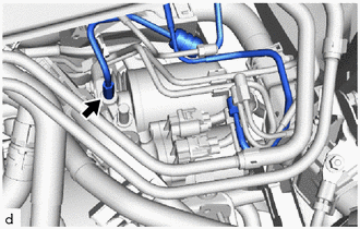
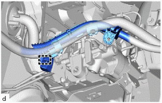
Using a 10 mm union nut wrench, remove the front No. 1 brake tube from the brake booster pump with bracket assembly.
-
-
REMOVE FRONT SUSPENSION CROSSMEMBER SUB-ASSEMBLY
-
REMOVE BRAKE BOOSTER PUMP WITH BRACKET ASSEMBLY
-
Disengage the clamp to separate the wire harness.
-
Disconnect the 2 brake booster pump assembly connectors.
-
Disengage the clamp to separate the front No. 4 brake tube from the brake booster pump with bracket assembly.
-
Disengage the clamp to separate the wire harness from the brake booster pump with bracket assembly.
-
Remove the bolt and wire harness clamp bracket from the brake booster pump with bracket assembly.
-
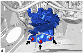
Remove the 3 nuts and brake booster pump with bracket assembly.
-
-
REMOVE NO. 1 BRAKE TUBE CLAMP BRACKET
-
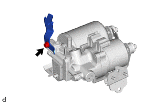
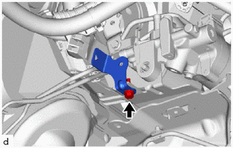
Remove the bolt and No. 1 brake tube clamp bracket from brake booster pump with bracket assembly.
-
-
REMOVE BRAKE BOOSTER PUMP ASSEMBLY
-
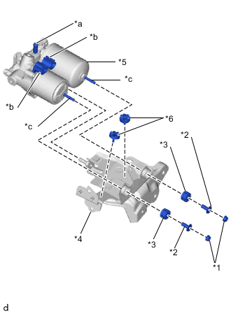
*1 Nut *2 Brake Actuator Case Collar *3 Brake Booster Pump Bushing *4 Brake Actuator Bracket Assembly *5 Brake Booster Pump Assembly *6 Brake Actuator Bracket Cushion *a Union *b Connector *c Stud Remove the 2 nuts, 2 brake booster pump bushings, 2 brake actuator case collars and brake booster pump assembly from the brake actuator bracket assembly.
Note
-
When handling the brake booster pump assembly, do not hold it at the parts marked *a, *b and *c in the illustration.
-
Do not drop the brake booster pump assembly when carrying it. Do not use a brake booster pump assembly that has been dropped.
-
Do not allow brake fluid to contact the inside of the connector.
-
-
Remove the 2 brake actuator bracket cushions from the brake actuator bracket assembly.
-