BRAKE BOOSTER(for RHD) REMOVAL
CAUTION / NOTICE / HINT
The necessary procedures (adjustment, calibration, initialization, or registration) that must be performed after parts are removed, installed, or replaced during the brake booster with master cylinder assembly removal/installation are shown below.
CAUTION / NOTICE / HINT
| Replacement Part or Procedure | Necessary Procedure | Effects/Inoperative when not Performed | Link |
|---|---|---|---|
| Replacement of brake booster with master cylinder assembly |
|
|
Note
While the auxiliary battery is connected, even if the power switch is off, the brake control system activates when the brake pedal is depressed or any door courtesy switch is turned on. Therefore, when servicing brake system components, do not depress the brake pedal or open/close the doors while the auxiliary battery is connected.
PROCEDURE
-
PLACE FRONT WHEELS FACING STRAIGHT AHEAD
-
PRECAUTION
Note
After turning the power switch off, waiting time may be required before disconnecting the cable from the negative (-) auxiliary battery terminal. Therefore, make sure to read the disconnecting the cable from the negative (-) auxiliary battery terminal notices before proceeding with work.
-
DISABLE BRAKE CONTROL
-
Wait for at least 2 minutes after turning the power switch off.
Note
When the brake pedal is depressed or the door courtesy switch is turned on even if the power switch is off, the brake control system activates. Therefore, do not depress the brake pedal or open/close the doors until the reservoir level switch connector is disconnected.
-
Disconnect the reservoir level switch connector with the parking brake applied.
-
Remove the luggage trim service hole cover.
-
Disconnect the cable from the negative (-) auxiliary battery terminal.
-
Depress the brake pedal 40 times or more to return all the fluid in the accumulator back to the reservoir.
-
Check that the brake pedal cannot be further depressed.
-
Release the parking brake.
-
-
REMOVE NO. 1 INSTRUMENT PANEL UNDER COVER SUB-ASSEMBLY
-
REMOVE BRAKE PEDAL RETURN SPRING
-
REMOVE PUSH ROD PIN
-
REMOVE WINDSHIELD WIPER MOTOR AND LINK
-
REMOVE NO. 1 HEATER AIR DUCT SPLASH SHIELD SEAL
-
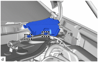
Disengage the 2 clamps to remove the No. 1 heater air duct splash shield seal from the outer cowl top panel sub-assembly.
-
-
REMOVE WATER GUARD PLATE RH
-
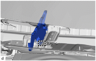
Disengage the clamp to remove the water guard plate RH from the outer cowl top panel sub-assembly.
-
-
REMOVE COWL BODY MOUNTING REINFORCEMENT RH
-
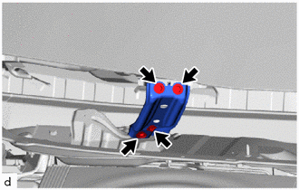
Remove the 4 bolts and cowl body mounting reinforcement RH.
-
-
REMOVE OUTER COWL TOP PANEL SUB-ASSEMBLY
-
Disengage the clamp to separate the wire harness from the outer cowl top panel sub-assembly.
-
for Cold Area Specification Vehicles:
-
Disconnect the windshield deicer connector.
-
Disengage the 3 clamps to separate the wire harness from the outer cowl top panel sub-assembly.
-
-
except Cold Area Specification Vehicles:
-
Disengage the 2 clamps to separate the wire harness from the outer cowl top panel sub-assembly.
-
-
Disconnect the hydrogen detector connector.
-
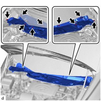
Remove the 9 bolts and outer cowl top panel sub-assembly.
-
-
DRAIN BRAKE FLUID
-
REMOVE BRAKE MASTER CYLINDER RESERVOIR WITH BRACKET
-
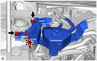
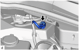
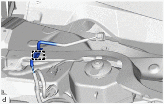
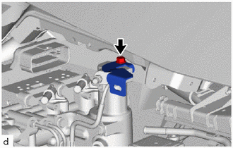
Disengage the clamp to separate the wire harness from the brake master cylinder reservoir with bracket.
-
Remove the 2 nuts to separate the brake master cylinder reservoir with bracket from the vehicle body.
-
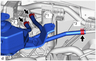
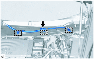
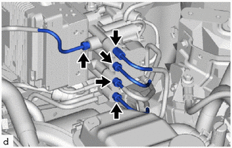
*1 No. 1 Reservoir Hose *2 No. 2 Reservoir Hose *3 No. 2 Brake Actuator Hose Slide the 3 clips and disconnect the No. 2 brake actuator hose, No. 1 reservoir hose and No. 2 reservoir hose from the brake booster with master cylinder assembly.
-
-
REMOVE BRAKE BOOSTER WITH MASTER CYLINDER ASSEMBLY
-
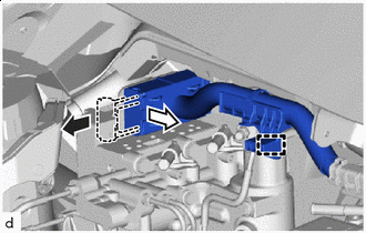

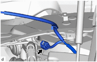
Release the lock lever 
Disconnect the connector Disengage the clamp to separate the motor compartment main wire.
-
Release the lock lever and disconnect the connector from the brake booster with master cylinder assembly.
-
Remove the bolt and wire harness clamp bracket.
-
Using a 10 mm union nut wrench, disconnect the 5 brake tubes from the brake booster with master cylinder assembly.
-
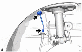
Using a 10 mm union nut wrench, disconnect the brake tube from the front flexible hose.
-
Disengage the grommet to remove the brake tube from the vehicle body.
-
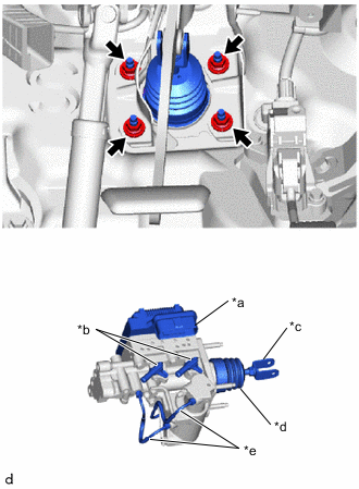
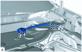
*a Connector Portion *b Union *c Push Rod Clevis *d Boot *e Brake Tube Remove the 4 nuts and brake booster with master cylinder assembly.
Note
-
Do not carry the brake booster with master cylinder assembly by the portion shown in the illustration.
-
Do not kink or damage the brake tubes.
-
Be careful not to allow the brake fluid to enter the removed connector.
-
-
-
REMOVE BRAKE BOOSTER GASKET
-
Remove the brake booster gasket from the brake booster with master cylinder assembly.
-