REAR AXLE BEAM REMOVAL

CAUTION / NOTICE / HINT
The necessary procedures (adjustment, calibration, initialization, or registration) that must be performed after parts are removed, installed, or replaced during the rear axle beam assembly removal/installation are shown below.
| Replacement Part or Procedure | Necessary Procedure | Effects/Inoperative when not Performed | Link |
|---|---|---|---|
| Rear height control sensor sub-assembly |
|
Automatic headlight beam level control system | |
| Rear shock absorber assembly LH |
|
VSC malfunctioning | |
| Adjust lane departure warning camera | Lane departure alert system does not operate correctly |
Note
-
When removing or installing the rear disc brake caliper assembly, if the piston of the brake caliper is pushed in, the clearance between the brake pad and rear disc will become large. In this condition, depressing the brake pedal may cause DTC C1214 (Hydraulic Control System Malfunction) to be stored, so check and clear DTCs after the procedure is complete.
-
With the auxiliary battery connected, even if the power switch is off, turning a door courtesy switch ON or operating the brake pedal will activate the brake control system, so disconnect the negative auxiliary battery terminal so that brake control is prohibited.
PROCEDURE
-
PRECAUTION
Note
After turning the power switch off, waiting time may be required before disconnecting the cable from the negative (-) auxiliary battery terminal. Therefore, make sure to read the disconnecting the cable from the negative (-) auxiliary battery terminal notices before proceeding with work.
-
DISABLE BRAKE CONTROL
-
REMOVE REAR WHEEL
-
DRAIN BRAKE FLUID
Note
If brake fluid leaks onto any painted surface, immediately wash it off.
-
REMOVE FRONT FLOOR CENTER COVER LH
-
REMOVE FRONT FLOOR CENTER COVER RH
-
REMOVE REAR SUSPENSION BRACE SUB-ASSEMBLY
-
Remove the 4 bolts and rear suspension brace sub-assembly from the vehicle.
-
-
SEPARATE SKID CONTROL SENSOR WIRE LH
-
SEPARATE SKID CONTROL SENSOR WIRE RH
Tech Tips
Use the same procedure for the RH side and LH side.
-
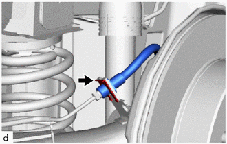
SEPARATE REAR FLEXIBLE HOSE LH
-
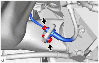
Using a 10 mm union nut wrench, and separate the rear No. 4 brake tube from the rear flexible hose LH.
Note
-
Do not kink or damage the brake lines.
-
Do not allow any foreign matter such as dirt or dust to enter the brake lines from the connecting parts.
-
-
Remove the bolt and separate the rear flexible hose LH from the rear axle beam assembly.
-
-
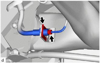
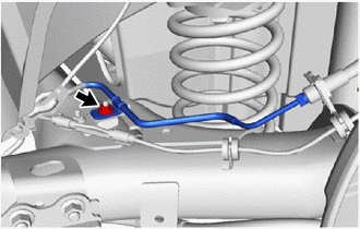
SEPARATE REAR FLEXIBLE HOSE RH
-
Using a 10 mm union nut wrench, and separate the No. 3 rear brake tube from the rear flexible hose LH.
Note
-
Do not kink or damage the brake lines.
-
Do not allow any foreign matter such as dirt or dust to enter the brake lines from the connecting parts.
-
-
Remove the clip and separate the rear flexible hose RH from the rear axle beam assembly.
-
-
REMOVE REAR DISC BRAKE CYLINDER ASSEMBLY LH
-
Using a 10 mm union nut wrench, and separate the rear No. 4 brake tube from the rear brake tube flexible hose.
Note
-
Do not kink or damage the brake lines.
-
Do not allow any foreign matter such as dirt or dust to enter the brake lines from the connecting parts.
-
-
Remove the clip and separate the rear brake tube flexible hose from the rear axle beam assembly.
-
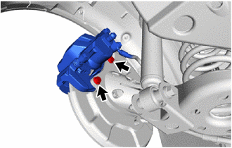
Remove the 2 bolts and rear disc brake cylinder assembly LH and rear brake tube flexible hose.
-
-
REMOVE REAR DISC BRAKE CYLINDER ASSEMBLY RH
Tech Tips
Use the same procedure for the LH side.
-
REMOVE PARKING BRAKE SHOE ADJUSTING HOLE PLUG
-
Remove the 2 parking brake shoe adjusting hole plugs.
-
-
REMOVE REAR DISC (for LH Side)
-
REMOVE REAR DISC (for RH Side)
Tech Tips
Use the same procedure for the LH side.
-
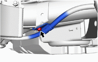
REMOVE REAR NO. 4 BRAKE TUBE
-
Remove the nut and rear No. 4 brake tube from the rear axle beam assembly.
-
-
REMOVE REAR NO. 3 BRAKE TUBE
Tech Tips
Use the same procedure for the rear No. 4 brake tube side.
-
REMOVE REAR AXLE HUB AND BEARING ASSEMBLY LH
-
REMOVE REAR AXLE HUB AND BEARING ASSEMBLY RH
Tech Tips
Use the same procedure for the LH side.
-
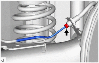
DISCONNECT PARKING BRAKE ASSEMBLY LH
-
Remove the bolt and separate the No. 3 parking brake cable assembly from the rear axle beam assembly.
-
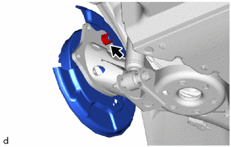
Remove the nut and separate parking brake assembly from the rear axle beam assembly.
Note
Hang the parking brake assembly LH by wire or similar.
-
-
DISCONNECT PARKING BRAKE ASSEMBLY RH
Tech Tips
Use the same procedure for the LH side.
-
SEPARATE REAR WHEEL HOUSE LINER LH
-
SEPARATE REAR WHEEL HOUSE LINER RH
Tech Tips
Use the same procedure for the LH side.
-
SEPARATE REAR HEIGHT CONTROL SENSOR SUB-ASSEMBLY
-
REMOVE REAR COIL SPRING LH
-
REMOVE REAR COIL SPRING RH
Tech Tips
Use the same procedure for the LH side.
-
REMOVE REAR COIL SPRING UPPER INSULATOR LH
-
REMOVE REAR COIL SPRING UPPER INSULATOR RH
Tech Tips
Use the same procedure for the LH side.
-
REMOVE REAR COIL SPRING LOWER INSULATOR LH
-
REMOVE REAR COIL SPRING LOWER INSULATOR RH
Tech Tips
Use the same procedure for the LH side.
-
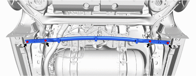
REMOVE REAR AXLE BEAM ASSEMBLY
-
Support the rear axle beam assembly with an engine lifter using 2 wooden blocks and 2 attachments or equivalent tools as shown in the illustration.
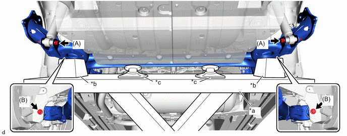
*a Engine Lifter *b Wooden Block *c Attachment - - Note
Make sure to secure the rear axle beam assembly to prevent it from dropping.
-
Remove the 2 bolts (A) and 2 nuts while holding the 2 nuts and separate the rear axle beam assembly from the rear shock absorber assemblies LH and RH.
Note
Because the nuts have their own stoppers, do not turn the nuts. Loosen the bolts with the nuts secured.
-
Remove the 2 bolts (B) and rear axle beam assembly from the vehicle.
-
-
REMOVE REAR AXLE BEAM DYNAMIC DAMPER LH
-
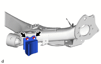
Remove the 2 nuts and rear axle beam dynamic damper LH from the rear axle beam assembly.
-
-
REMOVE REAR AXLE BEAM DYNAMIC DAMPER
Tech Tips
Use the same procedure for the LH side.
-
REMOVE REAR AXLE CARRIER BUSH LH
-
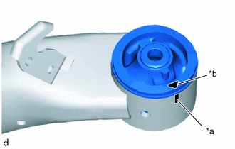
*a Matchmark *b Alignment mark When reusing the rear axle beam assembly:
-
Put a matchmark on the rear axle beam assembly so that it is aligned with the alignment mark of the rear axle carrier bushing LH.
-
-
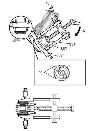
*a Bend Portion *b Turn *c Hold Using a chisel and hammer, bend the 2 ribs on the rear axle carrier bushing LH as shown in the illustration.
-
Using SST, remove the rear axle carrier bushing LH from the rear axle beam assembly.
- SST
- 09710-30041 ( 09710-03221 )
- 09950-40011 ( 09951-04020, 09952-04010, 09953-04030, 09954-04020, 09955-04011, 09957-04010, 09958-04011 )
- 09950-60010 ( 09951-00650 )
Note
-
Apply grease to the threads and tip of the SST center bolt before use.
-
When removing the rear axle carrier bushing LH, do not erase the matchmark on the rear axle beam assembly.
-
If the rear axle beam assembly is scratched, apply paint to the scratched areas of the rear axle beam assembly.
-
-
REMOVE REAR AXLE CARRIER BUSH RH
Tech Tips
Use the same procedure for the LH side.