REAR AXLE HUB REMOVAL
CAUTION / NOTICE / HINT
The necessary procedures (adjustment, calibration, initialization, or registration) that must be performed after parts are removed, installed, or replaced during the rear axle hub and bearing assembly removal/installation are shown below.
| Replacement Part or Procedure | Necessary Procedure | Effects/Inoperative when not Performed | Link |
|---|---|---|---|
| rear wheel alignment adjustment |
|
VSC malfunctioning | |
| Adjust lane departure warning camera | Lane departure alert system does not operate correctly |
Note
-
When removing or installing the front disc brake caliper assembly, pushing back the disc brake piston may cause a large clearance between the brake pads and brake disc. When the brake pedal is depressed with a large clearance between the brake pads and the brake disc, DTC C1214 related to abnormal brake fluid pressure may be stored. Make sure to clear DTC after performing this step.
-
While the auxiliary battery is connected, even if the power switch is off, the brake control system activates when the brake pedal is depressed or any door courtesy switch turns on. Therefore, when servicing the brake system components, do not operate the brake pedal or open/close the doors while the auxiliary battery is connected.
Tech Tips
-
Use the same procedure for the RH side and LH side.
-
The following procedure is for the LH side.
PROCEDURE
-
PRECAUTION
Note
After turning the power switch off, waiting time may be required before disconnecting the cable from the negative (-) auxiliary battery terminal. Therefore, make sure to read the disconnecting the cable from the negative (-) auxiliary battery terminal notice before proceeding with work.
-
DISABLE BRAKE CONTROL
-
REMOVE REAR WHEEL
-
DISCONNECT SKID CONTROL SENSOR WIRE
-
SEPARATE REAR DISC BRAKE CALIPER ASSEMBLY
-
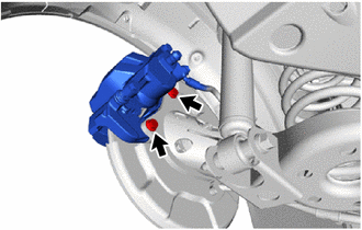
Remove the 2 bolts and separate the rear disc brake caliper assembly.
Note
Use wire or an equivalent tool to keep the rear disc brake caliper assembly from hanging by the rear flexible hose.
-
-
REMOVE PARKING BRAKE SHOE ADJUSTING HOLE PLUG
-
REMOVE REAR DISC
-
REMOVE REAR AXLE HUB AND BEARING ASSEMBLY
-
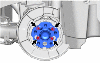
Remove the 4 bolts and rear axle hub and bearing assembly from the rear axle beam assembly.
-