REAR AXLE HUB BOLT REPLACEMENT

CAUTION / NOTICE / HINT
Note
-
When removing or installing the front disc brake caliper assembly, pushing back the disc brake piston may cause a large clearance between the brake pads and brake disc. When the brake pedal is depressed with a large clearance between the brake pads and the brake disc, DTC C1214 related to abnormal brake fluid pressure may be stored. Make sure to clear DTC after performing this step.
-
While the auxiliary battery is connected, even if the power switch is off, the brake control system activates when the brake pedal is depressed or any door courtesy switch turns on. Therefore, when servicing the brake system components, do not operate the brake pedal or open/close the doors while the auxiliary battery is connected.
Tech Tips
-
Use the same procedure for the RH side and LH side.
-
The following procedure is for the LH side.
PROCEDURE
-
PRECAUTION
Note
After turning the power switch off, waiting time may be required before disconnecting the cable from the negative (-) auxiliary battery terminal. Therefore, make sure to read the disconnecting the cable from the negative (-) auxiliary battery terminal notice before proceeding with work.
-
DISABLE BRAKE CONTROL
-
REMOVE REAR WHEEL
-
SEPARATE REAR DISC BRAKE CALIPER ASSEMBLY
-
REMOVE PARKING BRAKE SHOE ADJUSTING HOLE PLUG
-
REMOVE REAR DISC
-
REMOVE NO. 3 PARKING BRAKE SHOE RETURN TENSION SPRING
-
REMOVE BRAKE SHOE HOLD DOWN SPRING (for Front Side)
-
REMOVE REAR AXLE HUB BOLT
-
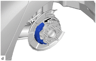
Pull the No. 1 parking brake shoe assembly towards the front of the vehicle by hand as shown in the illustration.
-
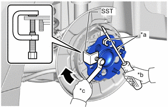
*a Service Nut *b Hold *c Turn Temporarily install 2 service nuts to the rear axle hub bolts as shown in the illustration.
Recommended Service Nut Thread diameter: 12.0 mm (0.472 in.) Thread pitch: 1.5 mm (0.0591 in.) Note
Install the service nuts to prevent damage to the rear axle hub bolts.
-
Using SST and a screwdriver or an equivalent tool to hold the rear axle hub and bearing assembly remove the rear axle hub bolt.
- SST
- 09611-12010
Note
Do not damage the threads of the rear axle hub bolts.
-
-
INSTALL REAR AXLE HUB BOLT
-
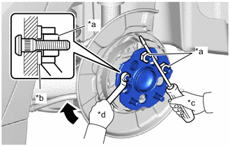
*a Service Nut *b Washer *c Hold *d Turn Temporarily install a new rear axle hub bolt to the rear axle hub and bearing assembly.
-
Install a washer and service nut to the rear axle hub bolt as shown in the illustration.
Recommended Service Nut Thread diameter: 12.0 mm (0.472 in.) Thread pitch: 1.5 mm (0.0591 in.) Tech Tips
Recommended washer thickness is 5 mm (0.197 in.) or more.
-
Using a screwdriver or an equivalent tool to hold the rear axle hub and bearing assembly, install the rear axle hub bolt by tightening the service nut.
Note
-
Install the service nuts to prevent damage to the rear axle hub bolts.
-
Do not damage the threads of the rear axle hub bolts.
-
-
Remove the 3 service nuts and washer from the 3 rear axle hub bolts.
-
Install the No. 1 parking brake shoe assembly.
-
-
INSTALL BRAKE SHOE HOLD DOWN SPRING (for Front Side)
-
INSTALL NO. 3 PARKING BRAKE SHOE RETURN TENSION SPRING
-
CHECK PARKING BRAKE INSTALLATION
-
INSTALL REAR DISC
-
INSTALL PARKING BRAKE SHOE ADJUSTING HOLE PLUG
-
INSTALL REAR DISC BRAKE CALIPER ASSEMBLY
-
ADJUST PARKING BRAKE PEDAL TRAVEL
-
INSTALL REAR WHEEL
-
CONNECT CABLE TO NEGATIVE AUXILIARY BATTERY TERMINAL
-
INSTALL LUGGAGE TRIM SERVICE HOLE COVER