HYBRID VEHICLE TRANSAXLE INSTALLATION
PROCEDURE
-
INSTALL TRANSAXLE BREATHER PLUG
-
Using a 14 mm deep socket wrench, install the transaxle breather plug to the FCV transaxle with motor assembly.
- Torque:
- 11.3 N*m { 115 kgf*cm, 8 ft.*lbf }
-
-
INSTALL TRANSAXLE HOUSING UNION
-
Coat a new O-ring with ATF, and install it to the transaxle housing union.
Note
Be careful not to damage or twist the O-ring.
-
Install the transaxle housing union to the FCV transaxle with motor assembly.
- Torque:
- 27 N*m { 275 kgf*cm, 20 ft.*lbf }
-
-
INSTALL OIL COOLER INLET TUBE SUB-ASSEMBLY
-
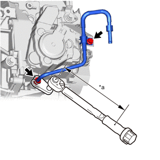
*a Torque Wrench Fulcrum Length Temporarily tighten the flare nut to install the oil cooler inlet tube sub-assembly to the FCV transaxle with motor assembly.
-
Install the No. 2 oil cooler tube clamp to the No. 1 oil cooler tube clamp with the bolt.
- Torque:
- 8.2 N*m { 84 kgf*cm, 73 in.*lbf }
-
Using a 17 mm union nut wrench, fully tighten the flare nut.
- Torque:
- Specified tightening torque
- 34.3 N*m { 350 kgf*cm, 25 ft.*lbf }
Note
While holding the transaxle housing union in place, tighten the flare nut.
Tech Tips
-
Calculate the torque wrench reading when changing the fulcrum length of the torque wrench.
-
When using a 17 mm union nut wrench (fulcrum length of 30 mm (1.18 in.)) + torque wrench (fulcrum length of 180 mm (7.09 in.)): 29.4 N*m (300 kgf*cm, 22 ft.*lbf)
-
-
INSTALL OIL COOLER UNION SUB-ASSEMBLY
-
Temporarily install the oil cooler union sub-assembly to the FCV transaxle with motor assembly with the union bolt and a new gasket.
-
Install the No. 2 oil cooler tube clamp to the No. 1 oil cooler tube clamp with the bolt.
- Torque:
- 8.2 N*m { 84 kgf*cm, 73 in.*lbf }
-
Fully tighten the union bolt.
- Torque:
- 35 N*m { 357 kgf*cm, 26 ft.*lbf }
-
-
INSTALL STRAIGHT SCREW PLUG
-
Using a 10 mm hexagon socket wrench, install the straight screw plug and a new gasket to the FCV transaxle with motor assembly.
- Torque:
- 43.5 N*m { 444 kgf*cm, 32 ft.*lbf }
-
-
INSTALL MOTOR CABLE BRACKET
-
Install the motor cable bracket to the FCV transaxle with motor assembly with the bolt.
- Torque:
- 8.0 N*m { 82 kgf*cm, 71 in.*lbf }
-
-
INSTALL NO. 2 AUTOMATIC TRANSMISSION CASE COVER
-
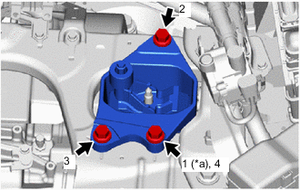
Temporarily install the No. 2 automatic transmission case cover to the FCV transaxle with motor assembly with the 2 bolts.
-
Fully tighten the 2 bolts in the order shown in the illustration.
- Torque:
- 8.4 N*m { 86 kgf*cm, 74 in.*lbf }
-
Install a new clip.
-
-
INSTALL FCV TRANSAXLE MASS DAMPER
-
Install the FCV transaxle mass damper to the FCV transaxle with motor assembly with the bolt.
- Torque:
- 30 N*m { 306 kgf*cm, 22 ft.*lbf }
-
-
INSTALL AUTOMATIC TRANSMISSION CASE COVER
-
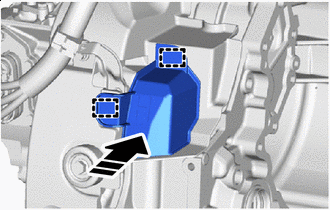

Install in this Direction Engage the 2 grommets to install the automatic transmission case cover to the No. 2 automatic transmission case cover.
-
-
INSTALL MOTOR CABLE
CAUTION:
Wear insulated gloves.
-
Engage the clamp to install the motor cable to the motor cable bracket.
-
-
INSTALL MOTOR MOUNTING BRACKET LH
-
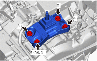
*a Temporarily Tighten Temporarily install the motor mounting bracket LH to the FCV transaxle with motor assembly with the 4 bolts.
-
Fully tighten the 4 bolts in the order shown in the illustration.
- Torque:
- 40 N*m { 408 kgf*cm, 30 ft.*lbf }
-
-
INSTALL REAR MOTOR MOUNTING BRACKET
-
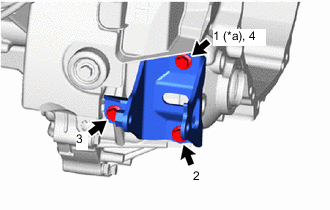
*a Temporarily Tighten Temporarily install the rear motor mounting bracket to the FCV transaxle with motor assembly with the 3 bolts.
-
Fully tighten the 3 bolts in the order shown in the illustration.
- Torque:
- 40 N*m { 408 kgf*cm, 30 ft.*lbf }
-
-
TEMPORARILY TIGHTEN REAR MOTOR MOUNTING INSULATOR
-
Temporarily install the rear motor mounting insulator to the rear motor mounting bracket with the bolt.
-
-
INSTALL FRONT MOTOR MOUNTING BRACKET
-
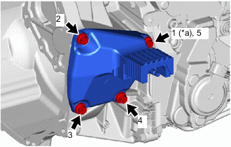
*a Temporarily Tighten Temporarily install the front motor mounting bracket to the FCV transaxle with motor assembly with the 4 bolts.
-
Fully tighten the 4 bolts in the order shown in the illustration.
- Torque:
- 40 N*m { 408 kgf*cm, 30 ft.*lbf }
-
-
INSTALL FRONT MOTOR MOUNTING INSULATOR
-
Install the front motor mounting insulator to the front motor mounting bracket with the nut.
- Torque:
- 40 N*m { 408 kgf*cm, 30 ft.*lbf }
-
-
INSTALL WIRE HARNESS CLAMP BRACKET
-
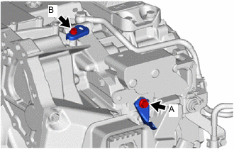
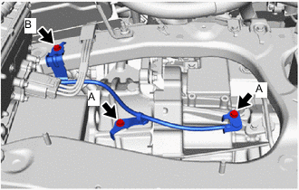
Install the 2 wire harness clamp brackets to the FCV transaxle with motor assembly with the 2 bolts.
- Torque:
- Bolt A
- 17.5 N*m { 178 kgf*cm, 13 ft.*lbf }
- Bolt B
- 13 N*m { 133 kgf*cm, 10 ft.*lbf }
-
-
INSTALL MOTOR WIRE
-
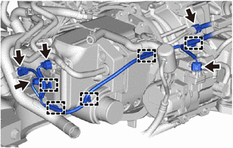
Engage the 7 clamps to install the motor wire to the FCV transaxle with motor assembly.
-
Connect the 3 connectors.
-
-
INSTALL FCV TRANSAXLE WITH MOTOR ASSEMBLY
-
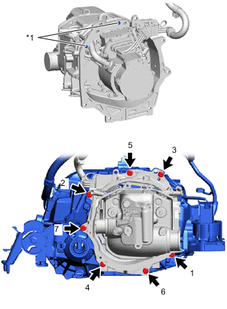
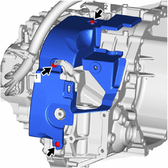
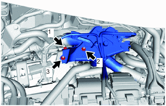
*1 Knock Pin Check that the 2 knock pins of the FC air compressor with motor assembly are not damaged.
-
Align the knock pins with the knock pin holes, and temporarily install the FCV transaxle with motor assembly to the FC air compressor with motor assembly with the 7 bolts.
Note
-
While preventing the housing of the FCV transaxle with motor assembly from touching the motor portion of the FC air compressor with motor assembly, install the FCV transaxle with motor assembly.
-
When installing, be careful not to pinch or catch any wire harnesses, etc.
-
Check that the contact surfaces are fully contacting with no gaps, and then tighten the bolts.
-
-
Fully tighten the 7 bolts in the order shown in the illustration.
- Torque:
- 46 N*m { 469 kgf*cm, 34 ft.*lbf }
-
Install the FC air compressor cable bracket to the FCV transaxle with motor assembly with the bolt.
- Torque:
- 8.0 N*m { 82 kgf*cm, 71 in.*lbf }
-
-
INSTALL MOTOR MOUNTING INSULATOR LH
-
*a Temporarily Tighten Temporarily install the motor mounting insulator LH to the center frame crossmember sub-assembly with the 3 bolts.
-
Fully tighten the 3 bolts in the order shown in the illustration.
- Torque:
- 72 N*m { 734 kgf*cm, 53 ft.*lbf }
-
Install the motor mounting insulator LH to the motor mounting bracket LH with the nut.
- Torque:
- 72 N*m { 734 kgf*cm, 53 ft.*lbf }
-
-
INSTALL FC COOLING WATER PUMP ASSEMBLY
-
Using an E8 "TORX" socket wrench, temporarily install the FC cooling water pump assembly to the FC air compressor with motor assembly with the 2 stud bolts.
- Torque:
- 10 N*m { 102 kgf*cm, 7 ft.*lbf }
-
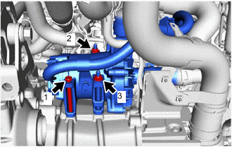
Install the bolt and 2 nuts to the FC cooling water pump assembly in the order shown in the illustration.
- Torque:
- 24.5 N*m { 250 kgf*cm, 18 ft.*lbf }
-
-
INSTALL FRONT SUSPENSION CROSSMEMBER SUB-ASSEMBLY
-
INSTALL FRONT SUSPENSION MEMBER REAR BRACE LH
-
INSTALL FRONT SUSPENSION MEMBER REAR BRACE RH
Tech Tips
Perform the same procedure as for the LH side.
-
INSTALL FRONT CROSSMEMBER SUB-ASSEMBLY
-
FULLY TIGHTEN REAR MOTOR MOUNTING INSULATOR
-
Fully tighten the bolt of the rear motor mounting insulator.
- Torque:
- 72 N*m { 734 kgf*cm, 53 ft.*lbf }
-
-
INSTALL REAR SIDE RAIL REINFORCEMENT SUB-ASSEMBLY LH
-
INSTALL REAR SIDE RAIL REINFORCEMENT SUB-ASSEMBLY RH
-
CONNECT NO. 1 MOTOR COOLING HOSE
-
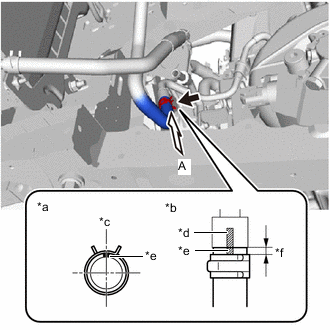
*a View A *b Hose End and Hose Clip Position *c Rear Side of Vehicle *d Tube Paint Mark (Pink) *e Hose Paint Mark (Red) *f Distance from Hose End to Hose Clip: 2 to 7 mm (0.0788 to 0.275 in.) Connect the No. 1 motor cooling hose to the oil cooler inlet tube sub-assembly and slide the hose clip to secure it.
Note
Align the hose and hose clip at the locations shown in the illustration and install them.
-
-
CONNECT NO. 3 MOTOR COOLING HOSE
-
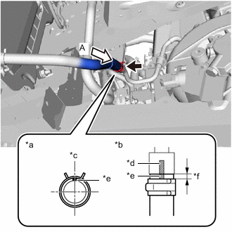
*a View A *b Hose End and Hose Clip Position *c Rear Side of Vehicle *d Tube Paint Mark (Light Blue) *e Hose Paint Mark (Blue) *f Distance from Hose End to Hose Clip: 2 to 7 mm (0.0788 to 0.275 in.) Connect the No. 3 motor cooling hose to the oil cooler union sub-assembly and slide the hose clip to secure it.
Note
Align the hose and hose clip at the locations shown in the illustration and install them.
-
-
INSTALL FC STACK COOLING WATER OUTLET BRACKET
-
Install the FC stack cooling water outlet bracket to the rear motor mounting insulator with the bolt.
- Torque:
- 19.5 N*m { 199 kgf*cm, 14 ft.*lbf }
-
-
INSTALL HYDROGEN PUMP CABLE BRACKET
-
Install the hydrogen pump cable bracket to the rear motor mounting insulator with the bolt.
- Torque:
- 19.5 N*m { 199 kgf*cm, 14 ft.*lbf }
-
-
INSTALL FRONT DRIVE SHAFT ASSEMBLY
-
PLACE FRONT WHEELS FACING STRAIGHT AHEAD
-
INSTALL NO. 1 STEERING COLUMN HOLE COVER SUB-ASSEMBLY
-
CONNECT NO. 2 STEERING INTERMEDIATE SHAFT ASSEMBLY
-
INSTALL COLUMN HOLE COVER SILENCER SHEET
-
INSTALL MOTOR CABLE
CAUTION:
Wear insulated gloves.
-
Engage the clamp to install the motor cable to the motor cable bracket.
-
-
INSTALL FCV TRACTION MOTOR BOND CABLE ASSEMBLY
-
Install the FCV traction motor bond cable assembly to the center frame crossmember sub-assembly, FC air compressor with motor assembly and FCV transaxle with motor assembly with the 3 bolts.
- Torque:
- 10.5 N*m { 107 kgf*cm, 8 ft.*lbf }
Bolt Length (not including head) Item Length Bolt A 16 mm (0.630 in.) Bolt B 15 mm (0.591 in.)
-
-
CONNECT MOTOR WIRE
-
Engage the 5 clamps to install the motor wire.
-
Connect the 5 connectors.
-
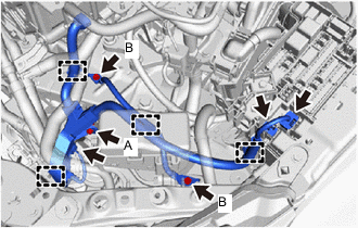
Engage the 4 clamps to install the motor wire.
-
Connect the motor wire with the 3 bolts.
- Torque:
- Bolt A
- 7.0 N*m { 71 kgf*cm, 62 in.*lbf }
- Bolt B
- 8.4 N*m { 86 kgf*cm, 74 in.*lbf }
Bolt Length (not including head) Item Length Bolt A 20 mm (0.787 in.) Bolt B 15 mm (0.591 in.) -
Connect the 3 connectors.
-
-
INSTALL NO. 1 RELAY BLOCK COVER
-
INSTALL UPPER NO. 1 RELAY BLOCK COVER
-
INSTALL INVERTER COOLING OUTLET PIPE
-
Install the inverter cooling outlet pipe to the electric heater sub-assembly with the 2 bolts.
- Torque:
- 8.0 N*m { 82 kgf*cm, 71 in.*lbf }
-
-
CONNECT NO. 1 INVERTER COOLING OUTLET HOSE
-
INSTALL FC COOLING WATER TEMPERATURE CONTROL VALVE
-
Temporarily install the FC cooling water temperature control valve to the electric heater sub-assembly with the bolt and 2 nuts.
-
Fully tighten the bolt and 2 nuts in the order shown in the illustration.
- Torque:
- 13 N*m { 133 kgf*cm, 10 ft.*lbf }
Note
When tightening, firmly press the FC cooling water valve bracket against each tightening surface of the electric heater sub-assembly bracket while tightening the bolts.
-
Connect the electric heater sub-assembly connector.
-
-
INSTALL FC COOLING BY-PASS PIPE
-
Install the FC cooling by-pass pipe to the electric heater sub-assembly with the 2 nuts.
- Torque:
- 8.0 N*m { 82 kgf*cm, 71 in.*lbf }
-
-
INSTALL FC COOLING WATER VALVE INLET PIPE
-
Install the FC cooling water valve inlet pipe to the inverter cooling outlet pipe with the 2 bolts.
- Torque:
- 8.0 N*m { 82 kgf*cm, 71 in.*lbf }
-
-
INSTALL FC RADIATOR INLET PIPE
-
Install the FC radiator inlet pipe to the center frame crossmember sub-assembly with the 2 bolts.
- Torque:
- 8.0 N*m { 82 kgf*cm, 71 in.*lbf }
-
-
INSTALL NO. 2 WATER HOSE SUB-ASSEMBLY
-
Engage the clamp to install the No. 2 water hose sub-assembly to the No. 1 FC cooling water valve outlet hose.
-
-
INSTALL HEATER WATER INLET B HOSE
-
Engage the clamp to install the heater water inlet b hose to the FC radiator inlet pipe.
-
-
INSTALL INVERTER WITH CONVERTER ASSEMBLY
-
ADD HYBRID TRANSAXLE FLUID
-
INSPECT AND ADJUST HYBRID TRANSAXLE FLUID
-
INSPECT FOR HYBRID TRANSAXLE FLUID LEAK
-
INSTALL FRONT FLOOR COVER RH
-
INSTALL FRONT FLOOR COVER LH
-
INSTALL REAR MOTOR UNDER COVER LH
-
INSTALL REAR MOTOR UNDER COVER RH
-
INSTALL NO. 2 MOTOR UNDER COVER
-
INSTALL NO. 1 MOTOR UNDER COVER
-
INSPECT AND ADJUST FRONT WHEEL ALIGNMENT